Thursday, September 30, 2010

Lab Exercise 5

Date:
30/9 2010

Duration of activity:
3.5 hours

Group members participating:
Frederik, Lasse & Christian

Goals:
The main goal is to make a robot follow a black line and stop at the end of the line in the goal zone[1].

Plan:
1. Build a robot and mount the light sensor
2. Test a program that distinguishes between black and white and investigate its behavior on different colors.
3. Run a program that uses the black/white sensor program to follow a line
4. From experiences with programs in 2. and 3. make a program that distinguishes between black, white and green
5. Finally the program from 4. shall be used to make a line follower that stops in a green goal zone.


Results:
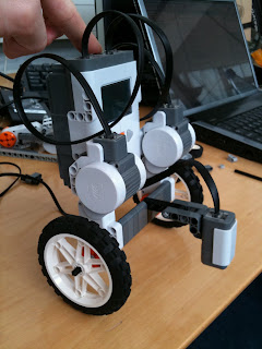
1. The robot was built according to the description in the Lego NXT Base Set 9797 building instructions page 32 to page 34. The result can be seen in action in section 3.

2. We modified the LineFollowerCal-class so instead of regulating the motors either black or white was written to display. Calibration values were black = 32, white =  59 and the threshold was then observed to be 44 although it should have been 46. This is probably because the values changed a bit during calibration.

3. The class LineFollowerCal was tested just to see how well a calibrated line follower performs. A video can be seen below.


4.We made a class called BlackWhiteGreenSensor[2] which extended the original BlackWhiteSensor with a green color. The test showed (as expected) that the robot detects green every time the color changes from white to black and vice versa.

5. Based on the observations made in 4. we wanted to improve both the SW and HW; replace the NXT sensor with two RCX sensors, improve BlackWhiteGreenSensor and use it with a new linefollower program.

We modified the robot by adding two RCX light sensors to be able to detect when we are inside or outside the black line. Image can be seen below:

Robot with two RCX light sensors


We added an enum to the BlackWhiteGreenSensor in order to get the current color. We also replaced the NXT light sensor by a RCX light sensor in the new BlackWhiteGreenSensor[3]. The idea about this is to use the same calibration values for both RCX sensors and we then only need to calibrate once a start up.

We made a new edition[4] of the previous line follower program by adding two RCX-sensors in the program. Apart from that we added a StopWatch-like functionality with the purpose of measuring how long time the sensor has measured green. When the time has passed the motors are stopped.

We wanted to have a minimum speed for each wheel so e.g. when turning a minimum speed of say 50 is applied to the motors. By experimenting we concluded that a minimum speed of around 50 was necessary to get the motor running.

The MotorPort class in the class Car was replaced by the Motor because we had problems getting the Motor to slow down fast enough, which was solved by using the Motor class. After that the robot performed quite good with a relatively high speed and able to stop in the goal zone.

Conclusion:
This exercise has shown that a calibration before doing the line following has a lot to say because the light condition varies a lot. A further improvement is replacing one light sensor with two. This makes the robot do a more real line following instead of just following the dividing line between black and white. To avoid the robot drives away from the track the motors need to be very responsive and we had the best results using the Motor class instead of the MotorPort class.

References:
[1] Lab Exercise 5 description - http://legolab.cs.au.dk/DigitalControl.dir/NXT/Lesson5.dir/Lesson.html
[2] BlackWhiteGreenSensor - http://dl.dropbox.com/u/2389829/Lego/Lab5/BlackWhiteGreenSensor.java
[3] Extended BlackWhiteGreenSensor - http://dl.dropbox.com/u/2389829/Lego/Lab5/BlackWhiteGreenSensorExtended.java
[4] LineFollower with 2 sensors -  http://dl.dropbox.com/u/2389829/Lego/Lab5/LineFollower.java

Thursday, September 23, 2010

Lab Exercise 4

Date:
23/9 2010

Duration of activity:
3 hours

Group members participating:
Frederik, Lasse & Christian

Goals:
Getting a robot balancing by gathering inspiration from various examples [1]

Plan:
1. Build the robot
2. Get the robot balancing

Results: 
1. The robot was built by following the instructions to the NXTway[2]. Later on we rebuilt the robot using the instructions from Brian Bagnall[3] and we then had a robot that matches the code.

2. We used the example from Brian Bagnall[3] as a starting point which is a PID controlled robot[4]. The robot was able to balance for a short period of time but was very unstable. When the robot got a little out of balance the robot fell down immediately. So we needed to modify the code to get it working. While tweaking the parameters we found out that the light conditions in the room has a lot to say. The slightest change in light intensity causes the robot to crash.
We tried to change the size of the wheels and it help of the responsiveness of the robot. Afterwards we rebuilt the robot a desribed in the chapter above (1.) but that wasn't succesful either. We decided to give the robot a higher center of gravity by building a tower on top of the robot, which can be seen on the picture below - that was no help.


As a last desperate attempt we built the robot more or less like the first attempt again. The main difference was that we moved the sensor away from the robot body in order to get a wider range of sensor values and avoid some of the shadow from the robot. We then tested the robot in a dark room and it actually performed quite well! The robot is seen below.


Below is a video showing our best result in daylight:


Conclusion:
We didn't manage to get the robot balancing more than 5 seconds in daylight even when we used programs that should be working and was tested on robots similar to the one we built.

By using the lightsensor to balance a robot it requires uniform light in the testroom to get the robot balancing properly. Also the surface has a lot to say; we experienced opposite behaviour when placing the robot on a table and on the floor. The best conditions for the robot has clearly been the dark room.


References:
[1] Lab Exercise 4 description - http://legolab.cs.au.dk/DigitalControl.dir/NXT/Lesson4.dir/Lesson.html
[2] NXTway building instructions: http://www.philohome.com/nxtway/bi_nxtway.htm
[3] Brian Bagnall, Maximum Lego NXTBuilding Robots with Java Brains, Chapter 11, 243 - 284
[4] PID controller, http://en.wikipedia.org/wiki/PID_controller


Thursday, September 16, 2010

Lab Exercise 3

Date:
16/9 2010

Duration of activity:
3.5 hours

Group members participating:
Frederik & Christian

Goals:
To investigate the NXT sound sensor, and the characteristics of different sound phenomenae - especially the gesture of clapping.

Plan:
1. Test of the Sound Sensor
2. Data logger
3. Sound Controlled Car
4. Clap Controlled Car

Results:
1. After mounting the sound sensor, and uploading the program SoundSensorTest [1] to the car, we could see the values of the microphone readings in the display of the car. We experimented  with different sampling frequencies in the main loop of the program to see, if this had any effect on how the readings were.
It seems that if the delay is below a value of around 300 ms, the microphone readings are not so responsive.

Car with mounted sound sensor

2. After a dry run of the datalogger program, SoundSensor [2], we inspected the sample file and decided to layout the data written by DataLogger [3] in a single row instead of 20 to ease the import of data to MS Excel.
In the start of the log file, it seems as if there is some noise - our guess is that it is some sort of burst noise [4] occuring during initialization of misc. circuits inside the NXT.
We imported the data sample into Excel, and made a graph:
As the graph shows, there is some form of impulse starting at sample 0, and quickly dying out. The clap starts at around sample #200, and peaks at 93 dB. The graph shows that the clap has a very characteristic, steep climb at the beginning, and then dies out more slowly.

3. The program SoundCtrCar [5] has 4 states; stopped, go forward, turn left, turn right. Each state transition is triggered by a sound input of 90 or higher.


Video showing the SoundCtrCar program

The program runs in a do-while loop, which continuosly reads the sound sensor until a value equal or above the threshold is read. It then returns to the main control loop.
One hickup with this version of the program is that it is difficult to terminate the program - the escape button must be pressed down before the main loop is restarted.

We wanted to improve this version by making the press of the escape button detectable from all program parts. We did this by making a class that listens for button presses by implementing the ButtonListener interface and adding a field indicating a press on the escape button. See example below.


 Then other classes will then be able to read a global value of the escape button. So by checking for the escape button in the waitForLoudSound method a press on the escape button terminates the program. See example below.


4. To recognize claps, Sivan Toledo suggests that you look at how fast the sound strength goes from low to high, and then back to low again. The leading edge of the clap should be very quick, and the trailing edge should be slower [6]. This is because of the nature of a clap; it starts very abruptly, and then dies out more slowly, but still quite fast.
We had intended to experiment if it would be possible to look at samples close to each other. E.g. if a sample would rise with a value of, say, 30-50, it might be possible to recognize the clap. Of course for it to be sure, we would have to look at the trailing edge in order to exclude a continous high strength sound.
For reasons unknown we were not able to upload our program to the NXT, and therefor we were not able to test our assumptions before time ran out. The program can be seen in [7].

Conclusion
Because of problems with uploading the Clap Controlled Car program, we did not succeed in testing our assumptions for clap recognition. Likewise we didn't get to investigate the characteristics of other sound phenomenae than clapping. However, sample files suggested, that Sivan Toledo is on to something, when he proclaims, that a clap has a short, and powerful rise, and a more subtle trail.

Implementation-wise the NXT sound sensor is similar in use to the other NXT sensors - the sensor is instantiated, and the method readValue() is used to gather data.


References

[1]. SoundSensorTest.java - http://dl.dropbox.com/u/2389829/Lego/Lab3/SoundSensorTest.java
[2]. SoundSampling.java - http://dl.dropbox.com/u/2389829/Lego/Lab3/DataLogging/SoundSampling.java
[3]. DataLogger.java - http://dl.dropbox.com/u/2389829/Lego/Lab3/DataLogging/DataLogger.java
[4]. Burst Noise, Wikipedia - http://en.wikipedia.org/wiki/Burst_noise
[5]. Ref to SoundCtrCar - http://dl.dropbox.com/u/2389829/Lego/Lab3/SoundCtrl/SoundCtrCar.java
[6]. Legolab exercise 3 - http://www.legolab.daimi.au.dk/DigitalControl.dir/NXT/Lesson3.dir/Lesson.html
[7]. ClapControlledCar.java - http://dl.dropbox.com/u/2389829/Lego/Lab3/Clap/ClapControlledCar.java

Tuesday, September 14, 2010

Lab Exercise 2

Date:
9/9 2010

Duration of activity:
3 hours

Group members participating:
Lasse & Christian

Goals:
Get to know the ultra sonic sensor by using different test setups and programs.

Plan:
1. Mount ultrasonic sensor on the Lego car built in Lab Exercise 1.
2. Do experiments with the ultrasonic sensor itself
3. Test the sensor for which distances it can measure
4. Test a TrackBeam program and analyse its behaviour.
5. Test a WallFollower program and follow an algorithm with different modifications.

Results:

1.We mounted the Ultrasonic sensor on the Lego car and compiled and uploaded the SonicSensorTest.java program without any problems.

2. We tried to modify the sampling frequency below 300 ms (default). Already at a sampling rate of 200 ms there was a noticeable difference in the update of sensor values. At 100 ms (and below) it was hard to see a noticeable difference compared to the 200 ms. This concludes that there is still a need for delay between readings but not as high as 300 ms.

3. We wanted to find the measuring limits of the sensor. To test the measurement limit of the sensor we tried measuring the maximum distance to different materials as shown in the table below.


In theory the sensor has a maximum reading limit of 254 cm. A return value of 255 means that no object has been detected. Since the speed of sound is 340.29 m/s a detection of a "no object" requires a minimum delay of 7,5 ms since objects within 255 cm will echo before this.


4. The Tracker program makes sure that the robot keeps a certain distance to objects in front of it.

We the sampling rate from 300 ms to 100 ms an observed obviouslly a faster correction rate from the robot. We lowered the delay to 10 ms and noticed an even faster correction rate. See videos below.

 300 ms

100 ms

10 ms


Other modifiable variables are:

  • Gain: proportial factor adjusting the power to the motor dependant on the distance to object. Small changes in distance yield high speed changes.
  • Minimum power: The minimum power necessary to drive the motors. Values below 60 (default) means that the car halts when the accumulated power does not exceed 60. This means that the car does not move distance error is near 0. Values above 60 means more aggressive speed variations. See video below for a value of 100.
     
Minimum power = 100
The control method is called a closed loop controller or feedback controller since the controller uses the error (difference) between reference and input to change output. Since we only have one input and output the system is called a SISO (Single Input Single Output) control system.

5. We translated the NQC program written by Philippe Hurbain to Java code. We didn't have time to test the threshold values properly, so we did not get the correct WallFollower-behavior from the car.

Conclusion

Experiments with different setups for the ultrasonic sensor has shown some of its properties. The distance the sensor is capable of measuring depends on the material which reflects the sound pulses. The less pulses scattered or absorbed the better reading distance. We also calculated that the time it takes for the pulses to return to the ultrasonic sensor is below 7.5 ms. We also showed that by adjusting different parameters in programs using the ultrasonic sensor both desirable and non-desirable behaviour can be achieved :-)

References

Exercise 2 description:
http://legolab.cs.au.dk/DigitalControl.dir/NXT/Lesson2.dir/Lesson.html

Thursday, September 2, 2010

Lab Exercise 1

Date:
2/9 2010

Duration of activity:
4 hours

Group members participating:
Lasse, Frederik & Christian

Goals:
  • Get the leJOS software running on own PCs
  • Be able to compile and upload a line follower program to the NXT brick
  • Build a Lego car equippeded with two motors and a light sensor
  • Do experiments with the light sensor
Plan:
First install the (USB) drivers provided by Lego and then the leJOS drivers in order to make sure the USB drivers will work.
Experiments with the light sensor will be done by using different colored Lego bricks.

Results:
We tried to install the leJOS plugin for NetBeans because it is our favourite java editor. After we'd been trying for about 2 hours we decided to install Eclipse and the matching plugin. We managed to get it installed after having some trouble installing it via URL. The solution was to uncheck the "Group items by category"-checkbox to be able to see the plugin and download it.
After setting the paths for the leJOS installation we were able to compile and upload programs to the NXT brick!

Afterwards we wanted to be able to compile and upload programs from another PC by following the same procedure. We ran into an error saying "Something went wrong" when trying to upload and we found out that the problem had to do with the "Java Build Path" in Eclipse. It turns out the "classes.jar" file must not be built as the last item - by moving it up on the list we managed to get it working.

There were no problems building the Lego car because a building instruction were provided in the Lego Mindstorms Edication Set.

We performed a series of readings from the light sensor on different colors. The different colors was from lego-bricks to get the same type of surface for all readings. The light sensor has a flood light which makes the sensor measure the reflected light from the surface. We measured with flood light (A), without flood light (B) and without flood light while blocking the ambient light (C).


Conclusion
We managed to get two PC's running with the leJOS software, installed the leJOS Eclipse plugin and was able to compile and upload programs.

The readings from the light sensor concludes that the light sensor is able to distinguish between black and white. Other colors are between these values and therefore harder to tell apart. The usage of the flood light ensures more consistent data in diferent lit environments. When not using the flood light the whole range of colors are affected by an offset depending on the ambient light which may compromise the sensor readings.

References
The instruction used for the Eclipse plugin (doesn't describe the solutions to the problems we had):
http://lejos.sourceforge.net/nxt/nxj/tutorial/Preliminaries/UsingEclipse.htm#7