Thursday, January 20, 2011

Project Conclusion

Our initial ambitions were to experiment with a balancing robot. We wanted to improve the balancing capabilities (compared to lab session work and previous projects with balancing robots) by doing experiments with different sensors and regulation methods. The addition of an accelerometer, which had not previously been used, should complement the existing balancing capabilities. Furthermore if everything went smooth we would extend the balancing to 2 axis.

The accelerometer, which in theory should yield a more precise output of angle than the gyrosensor, proved to be very sensitive and subject to noise. By introducing a complementary filter we were able to cancel out the noise and still compensate for gyro drift. The work required to solve these problems were more time consuming than expected. But since the accurate sensing of angle is alpha and omega to all balancing experiments this was time well spent.

We were able to produce a balancing robot using the standard segway wheel-regulation method with quite a successful result. The robot is able to keep its balance within a small area for more than 15 seconds. After this time period, the robot seems to start wandering backwards and forwards over increasing distances. This may be due to the physics law of lego, which causes the accelerometer to jiggle out of place. But it may also be the PID constants that can be optimized. Since we did not want to focus solely on this design, we are satisfied with this result.
In our experiments with alternate balancing techniques, we found that the physics involved are somewhat more complex than with the "traditional" segway-style.

In the experiment with mass displacement, we experienced Newton's third law in action: When we pushed the mass in one direction, the robot got "pulled" in the opposite direction, and thereby got even more unstable. Besides this, the construction wasn't optimal built, as we could not displace the mass enough for it to have any practical effect on the robot - the angle from which the robot could be recovered was not great enough.

The experiment with the inverted pendulum on top of the robot showed us, that the torque exercised on the robot, by the motor turning the pendulum, made the robot unstable by "pulling" it in the wrong direction. This, and the fact that we now were trying to balance an inverted pendulum with two pivot points, caused that we were not successful in making the robot balance.
The PC application and the Bluetooth communication with the NXT proved to be a very useful tool for us. The robot works independently of the Bluetooth communication and the connection is therefore optional. The graphs on the PC GUI give a great understanding of the sensor values and the robot response impact and it has been easy to spot errors, optimizations and wrong signings (-/+) without debug-printing values to the NXT-screen (which is both inconvenient and resource demanding).
If given 2 more weeks to work with our project there are a few things that would be of interest.

As it is now the robot (traditional segway) is not balancing completely perfect and a way to improve the performance is by tuning the PID parameters. The tuning of these would require some time of precise work and focus; time we did not want to spend during the project but that would improve the balancing capabilities. Also since we based our physical construction of the robot upon a 3rd party project, it could be interesting to experiment with other robot constructions - ex. changing center of gravity by making a taller robot or/and by placing some weight on either side of the robot.
Since we did not succeed in getting any of the alternate balancing techniques to balance properly it would be valuable to scratch a little deeper into the surface of how mass displacement works. The physical construction of the robot and the mass displacement mechanism, could be optimized to improve performance on these techniques.
We had to give up on the idea of constructing a 2-axis balancing robot because of the time spend to implement the accelerometer and compensate for gyro drift. Even though it was our initial hope, it would only be possible if everything else went smoothly. And as it allways is, it didn't. But when looking at the ground we have covered during our project, we are very satisfied with the end result.

Friday, January 7, 2011

Project Session 6

Date:
07/01 2011

Duration of activity:
5½ hours

Group members participating:
Frederik, Christian & Lasse

Goals:
Do experiments with new physical regulation methods

Plan:
1. Construct a robot similar to the existing one, and mount a weight shifting device on top of it.
2. Do experiments with a new physical regulation method using weight shifting.
3. Construct a robot similar to the existing one, and mount an arm on top of it, acting as an inverted pendulum.
4. Do experiments with a new physical regulation method using an inverted pendulum.

Results:
1. Construction of robot with mass displacement
The main idea of the new balancing method is to displace a mass back and forth to counteract if the robot is toppling over. This is illustrated on Figure 1.

Figure 1 - The new regulation method illustrated. A mass is placed across the robot, and displaced according to the current angle of the robot.

In order to displace the mass mounted on top of the robot it was necessary to construct a mechanism consitisting of gears, and a motor. This contraption is shown on Figure 2 and Figure 3.

 Figure 2 - Full view of the robot with the new balancing mechanism.


Figure 3 - Closeup of the weight shifting mechanism

In each end of the balancing stick we attached some mass in the form of several wheels.

As this device consisted of Lego Mindstorms parts for the structure, and some Lego Technic parts for the gear and rack, the cogwheel and the rack fitted very tightly. This was allieviated by using one of the long Mindstorms parts to build a sort of a slide. Unfortunately we didn't get any pictures of this little tweak.

2. Experiments with mass displacement
We tried using the well-known setPower()-method in the Motor-class for controlling the displacement. As with all physical changes to the robot, this required adjustments to the PID-values.
The downside to this method, however, was that we had no monitoring of travelled distance. This would be nice in order to control more easily where the mass should be shifted to.

Because of this we tried to use the rotateTo()-method in the Motor-class. This method uses the tacho-counter in order to give a perception of the distance the rack travels.
We found out, however, that this method takes much more time to use than setPower(). Our findings were that rotateTo() is about 10 times slower than setPower() (22 ms vs. ~200 ms).

Because of the increased time consumption of rotateTo() the sample rate of the sensors were now decreased. Because of this the class CumulativeSensor was made into a thread with the responsibilty to sample the accelerometer and gyrometer.

When dealing with displacement of af balancing stick, it is necessary to monitor/control that the stick isn't pushed beyond its endpoints. For this, rotateTo() was adjusted so that this would not happen.
The maximum travel length of the rack was set to 6.0 cm to each side.

The code - from the class Tilde [2] - below shows how, and with which value rotateTo() was used.


As rotateTo() uses degrees and not distances as parameter to set motors, the maximum travel distance of the rack is converted to a degree, after which it is converted to a percentage. This is in order to set the wanted travel distance, which is calculated from the PID-value.
The motor power is set (in this example this is full power), and rotateTo() is called with the wanted degree-value.

We considered using the class TachoPilot but we chose not to, as we assessed that the advantage of this wasn't big enough. The advantage by using TachoPilot is that the travel distance can be set explicitly, but we still needed to do some "manual" calculations, which was why we opted this out.
We started out using a cogwheel with a diameter of 24 mm. In order to investigate if there was any improvement in the speed with which the mass was shifted, we tried with a bigger cogwheel (diameter 40 mm). As Video 1 shows, this didn't give any major improvements.

Video 1 - Mass displacement regulation

After this we experimented with making the balancing stick longer as seen Figure 4. This didn't give any improvements on making the robot balance, as the reaction time wasn't fast enough.

Figure 4 - Longer balancing stick

Up until now the speed with which the mass was displaced depended on the angle of the robot, i.e. the bigger the angle, the faster the balancing stick should move.
To see if it would have any difference to just use max speed all the time, we set the speed with setPower(100). This didn't yield any improvement in form of the ability to balance.

We discovered that when the balancing stick was in one of the outer positions, it was not possible to recover if the robot's angle was more than a few degrees. We tried to improve this by adding more weight to the balancing stick, but this had little or no effect.

As a last attempt to get the mass displacement method to work, we tried an alternative construction. Instead of a stick with weights in both ends we tried to use a single weight. This construction is shown on Figure 5. Our thought was that this should be faster to regulate, as the stick shouldn't have to move as far as the model with two weights.
The result of this was that angle we could recover from  was even smaller than before.

Figure 5 - Single weight


3. Construction of robot with inverted pendulum
The idea with the inverted pendulum [1] method is - like the mass displacement method - to counteract toppling by shifting the weight back or forth. The concept is shown on Figure 6.

Figure 6 - Concept of inverted pendulum construction

This construction was much easier to build than the previous one, as this construction basically consisted of a motor on the side of the NXT brick, and some "girders" to stabilize it. This is shown on Figure 7.

Figure 7 - Robot with inverted pendulum


4. Experiments with inverted pendulum
We tried this construction with both a long arm and a short arm on the pendulum to see if one would work better than the other. The results can be seen on videos 2 and 3.


Video 2 - Long arm inverted pendulum

Video 3 - Short arm inverted pendulum

As the videos show this wasn't the great succes either. It seems as though the long armed robot has the best preconditions for balancing, as it is better to salvage the robot than the small armed one.

Conclusion:
What we found from this experimental session is that it is much more difficult to make a robot balance using counterweights on the top than wheels at the bottom. The physics involved seems much more complex using these methods, and as software engineers we do not have the needed knowledge to sort this out.

Besides the complexity of the physics we found that rotateTo() isn't fast enough to use for this kind of balancing. The speed of the regulation isn't great enough to avoid the robot from falling.

Furthermore we made the balancing stick too limited in its travel length. We guess that if the balancing stick could have been pushed further out, that the robot would have a better chance to gain balance. This could possibly have been allieviated by mounting even more weight at the ends in order to balance and regulate properly.

As for the increase in the complexity of the involved physics, this was especially the case for the experiment with the inverted pendulum. This is because the robot itself acts as an inverted pendulum, and thereby we had to balance a pendulum with two pivot points, as shown on Figure 8.
 Figure 8 - Pivot points of the double inverted pendulum

Another issue with these balancing methods is that the torque produced by the motor on the balancing stick or pendulum is contributing to make the robot lose its balance - it pulls itself down when trying to regulate. It seems as if it's only when the weight has shifted fully either back or forth, that the robot gets "pulled" in the right direction by the momentum of the mass.

We thought that some of these problems could be minimized by using an "active", regular pendulum for balancing, controlled by a motor - see Figure 9 for the concept.
Figure 9 - Regular pendulum

With this method we would not have the problem of trying to balance two pendulums on top of eachother. Furthermore we would not have the issue with the two weights more or less "cancelling" eachother out. What problems could surface from the before mentioned issue with torque pulling the robot down we cannot say, as we unfortunateliy did not have time for this experiment.

The code for this session is found here: NXT [3] and PC [4].

References:
[1] Inverted pendulum, Wikipedia, http://en.wikipedia.org/wiki/Inverted_pendulum
[2] Tilde class, session 6, http://dl.dropbox.com/u/2678729/Lego/P_session6/Tilde.java
[3] L., Rasmussen, F., Laulund & C., Jensen, Session 2 source code on NXT, http://dl.dropbox.com/u/2678729/Lego/code/Session%206%20NXT%20source%20code.zip
[4] L., Rasmussen, F., Laulund & C., Jensen, Session 2 source code on PC, http://dl.dropbox.com/u/2678729/Lego/code/Session%206%20PC%20source%20code.zip

Monday, January 3, 2011

Project Session 5

Date:
03/01 2011

Duration of activity:
5 hours

Group members participating:
Frederik, Christian & Lasse

Goals:
Get the robot to be more responsive to changes in angle and hopefully make it balance satisfactory

Plan:
1. Do experiments with the adjustable values for complementary filter and PID controller [5]
2. Optimize the control loop to make the robot more responsive
3. Experiment with replacing the current PID controller with a PD controller
4. Investigate the use of small angle approximation

Results:

1. Adjusting regulation values
Last session we concluded that the response time was way too slow to be able to balance the robot. We thought the source of error was the filter values used in the high- and and low pass filters but it showed not to be the main problem.
After observing the results from the previous session via the PC application, we noticed that the accelerometer angle and the gyro angular velocity were opposite. The reason for this, was that the gyro sensor and accelerometer are placed on opposite sites of the robot hence having opposite understanding of direction. The solution was simply to invert the gyro velocity value which resulted in the values for accelerometer and gyro now being in synch as seen on Figure 1.

Figure 1 - Shows that the gyro velocity interpretation (yellow) is now synchronized with the calculated angle from accelerometer (red). The response is now way faster(green)

In order to find the optimal values for the constants P, I and D in the regulation logic, we used the manual callibration approach [4,6]. By using the PC application we were able to change the constants live, hence seeing the effects immediately. First the P was incremented until a point where the robot was oscillating around the point of balance. This effect was accomplished at ~30. Next the I was callibrated by halfing P and incrementing I stepwise. At ~3 the effect of I meant that the robot was able to find a "sweet" spot at where it was standing perfectly still - as opposed to oscillating. The calibration of D was the same approach and should have the effect that the robot would respond rapidly to ex. touching/pusing.

We found that the optimal values for the PID constants was P = 13, I = 3.3, D = 3.7.

Motor effect:
We noticed that much of the time when the robot was balancing, the motors made a squeaking sound even when not turning the wheels. We found that this was due to a minimum motor power (at power = 5) at which the wheels was turning. This could recommend the use of a constant minimum power of 5 applied to the motors, where the regulation could control the remaining 95. But we decided not to implement this, since the minimum value are so low.

Motor difference:
When balancing the regulation of the wheels are not always equal on both motors. This causes the robot to rotate, when one motor is effected more than the other. This has no direct negative effect on the regulation itself other than the imperfect look of the robot movement, which is not directly forward and backwards as one would expect. We tried using different combinations of motor ports as we know that this had an effect in previous lab sessions. But the result remained the same.
A solution for this imperfection would be to use the tacho-counter to keep track of motor difference and thereby wheel movement. When one motor is behind on the tacho count this could be corrected for by effecting this motor more. This was the solution used in the Marvin project [1], and it now occured to us what the meaning of the tacho-part of the Marvin code that we, until now, had not fully understood.

Accelerometer setpoint:
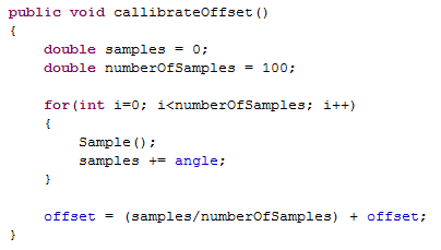
Because of the physical construction of the robot, the accelerometer reading at balance position are not ~0. This means that an offset had to be callibrated in order to get readings at ~0 when in balancing position. We decided to hardcode the offset as the offset should be constant.

The callibration had to be done manually by holding the robot in balancing position and reading from the accelerometer over an interval of time. The holding of the robot meant that it is not possible to hold it perfectly still and therefor it became somewhat of a trial and error approach. Some of the results are seen below:

Offset 3.707 - robot drives a bit forward.
Offset 3.9 - robot drives a bit backwards.
Offset 3.8 - acceptable behaviour.


Complementary filter optimization:
With the implementation of a complementary filter we were able to "trust" the gyro and accelerometer readings respectively. So we wanted to find a perfect combination of the values where the filter compensates for gyro drift and does not let the accelerometer noise affect the result.

Gyro: 0.98, Acc: 0.02 - Default values from last time.
Gyro: 0.90, Acc: 0.10 - Too affected by accelerometer noise.
Gyro: 0.99, Acc: 0.01 - Best result.

These values are callibrated with the regulation loop running in cycles of 25ms. If the loop cycle time is changed it will have an imediate effect on the filter result as the idea of the filter is to average over time. We therefore decided not to further change the cycle time of the regulation loop.

2. Optimizing of the control loop
We earlier discovered that display outputs are a demanding task for the NXT. It should therefore always be a priority to limit the number of ouputs to a minimum. We therefore removed all outputs from the regulation loop, as these were only for debug use.

In order to make sure that the regulation loop is performed in constant intervals we used System.getSystemMilisecs(). With every regulation cycle a timestamp is saved and used post regulation to calculate the execution time of regulation. The sleep time can thereby be derived from the execution time and guarantee a constant regulation cycle interval.


The Bluetooth thread printed "sending" / "receiving" to the display in every cycle. It should be possible to limit the output, as it will rarely be receiving from the PC when running, hence printing "sending" with every run. We implemented a boolean flag to make sure that there is only printed to the display when state changes between sending/receiving.


3. PD controller
In the current PID controller, Integral error and Derivative error are derrived from proportional error (angle). An alternative to this solution is to use a PD controller [3], that uses the proportional error (angle) and the derivative angle from the gyrosensor. This should in theory yield the same result as proportional_error - last_proportional_error as the current controller is using. But since we have the derivative error factor expressed by the gyrosensors output (angular velocity), this would seem like an obvious choice. We decided not to use this method, but merely recognize it, as an alternative.

4. Small angle approximation
By doing some research online on the accelerometer angle calculation we discovered a method called small angle approximation [2] as illustrated on Figure 2. The reasoning behind using an alternative angle calculation is to limit the ressources needed for calculation. Our current trigonometric calculation is stated to be quite resource demanding whereas the small angle approximation should be able to do the same ange calculation with less resources - as long as angles are within -30 to 30 degrees.

Figure 2 - Small angle approximation. The value of the small angle X in radians is approximately equal to its tangent (Wikipedia)

By experimenting with both calculation and printing the calculation time required we observed that the small angle approximation was ~twice as fast as the trigonometric calculation. Although the time gained was only ~1ms we decided to use the small angle approximation as it is, none the less, faster.

Conclusion:
We are now able to present a balancing robot that is stable for more than a few seconds! The drift in the gyro and the noise in the accelerometer are both practically eliminated by using the complementary filter. The wheels are not in sync which makes the robot dance in circlular movements but this is not a critical error.

The optimization of the control loop ensures a fast and consistent regulation time which is an important factor when designing a fast response demanding system like ours.

There are still problems with balancing over longer periods of time. This may depend on both the gyro drift which are not totaly compensated for with our factors in the filter - but we expect it to be the offset of the accelerometer which may not be perfectly callibrated. And when moving over time the physical laws of lego makes the accelerometer shake out of place making the robot wander in one direction.

The implementation of the small angle approximation calculation is just as precise as the trigonometric calculation and at the same time less resource demanding. With the use of small angle approximation we are only able to read angles between -30 and 30 degrees. This has the side-effect that we are not able to read accelerometer values when robot is lying flat on table which  could have been usefull for callibration. But the hardcoded value should be just as good.

A video of the resulting balancing robot is seen below on Video 1. This shows that there is still room for improvements but is by far the best performance compared to the other sessions. The final code for the robot is found here: NXT [7] and PC [8].


Video 1 - The resulting and final video of the balancing robot. 

References:
[1] Johnny Rieper et al., "Marvin NXT"http://wiki.aasimon.org/doku.php?id=marvin:marvin
[3] PD Controller, Fred G. Martin, Robotic Explorations: A Hands-on Introduction to Engineering, Chapter 5, pp. 179-190, Prentice Hall, 2001.
[4] PID manual tuning, Wikipedia, http://en.wikipedia.org/wiki/PID_controller#Manual_tuning
[5] Vance J. VanDoren, Understanding PID Control, http://legolab.cs.au.dk/DigitalControl.dir/phys253lab5-PIDPrimer.pdf
[6] A PID Controller For Lego Mindstorms Robots, http://www.inpharmix.com/jps/PID_Controller_For_Lego_Mindstorms_Robots.html
[7] L., Rasmussen, F., Laulund & C., Jensen, Tilde final NXT code - Session 5, http://dl.dropbox.com/u/2389829/Lego/Session%205/Session%205%20NXT%20final%20source%20code.zip
[8] L., Rasmussen, F., Laulund & C., Jensen, Tilde final PC code - Session 5,  http://dl.dropbox.com/u/2389829/Lego/Session%205/Session%205%20PC%20final%20source%20code.zip

Sunday, January 2, 2011

Project Session 4

Date:
02/01 2011

Duration of activity:
5 hours

Group members participating:
Christian & Lasse

Goals:
Get an understanding of the possibilites for more advanced sensor fusion [5],  and implement a suitable solution.

Plan:
1. Use the final code from last session, and try to improve the result using calibration and tuning of system parameters.
2. Investigate the possibilities for using an acknowledged filter for sensor fusion.
3. Implement a new balancing routine using a complementary filter.

Results:

1. Using calibration and tuning
Our efforts from last session showed that resetting the gyro angle based on an accelerometer reading didn't improve the balancing much. The robot (and accelerometer) was too unsteady for the gyro angle to be reset often enough. We will give the strategy a last try by calibrating the offset at startup, tuning the PID values, and then hopefully give the accelerometer better conditions for resetting the angle.

To make the robot move more smoothly we removed the normalization-part when regulating the motors. This change has the benefit that it is easier for the robot to make small angle adjustments instead of a more oscillating behaviour when using normalization. Furthermore it is not possible for the robot to stand still when using normalization.

We did some PID experiments by tuning the values manually. It was hard too observe any improvements because the gyro drift still influenced the resulting behaviour. Video 1 shows an example of a simple tuning where P equals to 35, I and D are both set to 0. Here it is obvious that the P-value is set too high, but the only way to set the right value is by experimenting. After a bit of tuning we concluded that a P-value around 30 and I and D values under 4 seemed to make the robot fairly steady, but unfortunately not steady enough for accelerometer to reset the gyro angle frequently enough. So we gave up the idea of using this method for sensor fusion.


Video 1 - Robot with PID values: P=35, I=0, D=0

2. Filters for sensor fusion
We have found a great explanation on using an accelerometer and gyro for balancing using filters [1]. The source included a tutorial on filters for balancing plus C source code which motivated us for using filters because we (as IT engineers) have a minimum knowledge about digital filters. Below is a brief description of the most obvious solutions for using accelerometer and gyro for balancing. For further explanation see the source mentioned above.

2.1 Accelerometer-assisted gyro

This was our self-invented method and the first attempt to combine the accelerometer and the gyro which is sketched on Figure 1. 

Figure 1 - The concept behind the first attempt to combine accelerometer and gyro.

Here the gyro both provides the angle and angular velocity. The angle is derived from integration, and is simply calculated like  
angle += gyro_velocity * time_since_last_sample

Which is similar to what simple physics say:
distance travelled = speed * time taken.
- in which calculated angle corresponds to the distance travelled.

As explained earlier the accelerometer sets the angle to 0 when it detects that the robot is upright to eliminate the gyro from drifting.

2.2 Complementary filter
The complementary filter aims to eliminate both the noise on the accelerometer and the drift in the gyro. This is done by using a low-pass filter on the accelerometer and thereby eliminating short-term fluctations. Gyro drift is cancelled out by using a high-pass filter as shown on Figure 2. 


Figure 2 - An overview of the complementary filter used for balancing

The idea is to use both the accelerometer and gyro for the angle calculation (combined with integration) and to be able to set how much we trust (weight) in the gyro and the accelerometer like:


Here the complementary part is illustrated by 0.98 and 0.02 which adds up to 1. The larger the value in front of the gyro term is (the high-pass filter), the more drift is allowed, and less for the accelerometer derived angle (the low pass filter).

2.3 Kalman filter
Figure 3 shows a sketch of the third and most advanced filter - the Kalman filter. As mentioned in session 3 we haven't studied the filter in depth because of its complexity, and as a consequence of the time consumption needed for understanding the filter sufficiently.


Figure 3 - Overall view of the concept for fusing accelerometer and gyro with the use of the Kalman filter

The overall concept is to use measurements that are observed over time that contain noise and other inaccuracies, and produce values that tend to be closer to the true values of the measurements and their associated calculated values. This is done by using an internal state model as shown in context on Figure 3 and more detailed on Figure 4.

Figure 4 - Model underlying the Kalman filter. Squares represent matrices. Ellipses represent multivariate normal distributions (with the mean and covariance matrix enclosed). Unenclosed values are vectors (image and text from Wikipedia). 

2.4 Our choice
After studying the possibilities we ended up choosing the complementary filter because it seemed like a reasonable compromise between our failed self-invented method and the Kalman filter. The complementary  filter is said to have nearly the same performance as the Kalman filter but should be less processor intensive [1]. We then decided to try out the complementary filter and if the performance shows to be unsatisfactory, the Kalman filter will be our last resort. 

3. Using the complementary filter
In order to derive the complementary angle we needed to calculate the angle using the accelerometer. This was done by using trigonometry which included measurements from two axes. Apart from that, variables for converting from radians to degrees and to compensate for the accelerometer offset were also needed - as shown below from the class Accelerometer [4]. The angle_offset_scale was needed because there was a small offset in the angle calculation. This value was found during experiments.

To actually join the two sensors in code we created a class named CumulativeSensor [3] with the responsibility of controlling the sampling of the gyro and accelerometer sensors, and making the complementary angle publicly accessible:


After having the structure in place we decided to remove unnecessary code - e.g. writing to the robot LCD. We discovered that writing to the LCD panel consumes quite a lot of processor time; by reducing the number of writings from 5 to 2 the duration of the control loop was reduced from approximately 35 ms to approximately 25 ms.
The Bluetooth thread, however, didn't have any measurable influence on execution time.

Afterwards we added the values accelerometer angle, gyro velocity and overall filtered angle to the PC application in order to monitor the variables. We noticed that the overall angle calculation was very slow to catch up with change in accelerometer angle. Figure 5 shows the result from the calculated accelerometer angle, the gyro velocity and the overall filtered angle. 

Figure 5 - Shows the monitoring of the three values  gyro velocity (yellow), calculated angle from accelerometer (red), and the complementary angle from CumulativeSensor (green)

Consequently one of the goals for the next session will be to improve the response time because, as it is now, the response time is way too slow to make the robot capable of balancing. We are quite sure that the lag isn't caused by limitations in the CPU-speed of the NXT but instead a correctable error in the filter. Apart from the slow response time it seems like the accelerometer noise and the gyro drift are less noticeable, so we are on the right track. 

Conclusion:
This session has been very rewarding; we have dropped the self-invented method for sensor fusion and found a method that seems very promising. There are still some hurdles to overcome but we are quite sure that it is possible to reach our goal using the chosen complementary filter. Furthermore experiments need to be done to reach an acceptable balance between gyro drift and accelerometer noise.

The code for this session is found here: NXT [6] and PC [7].

References:

[1] The DIY Segway - http://web.mit.edu/first/segway/segspecs.zip, filter.pdf, MIT, 2008
[2] Kalman Filter - http://en.wikipedia.org/wiki/Kalman_filter,  Wikipedia
[5] Fred G. Martin, Robotic Explorations: A Hands-on Introduction to Engineering, Chapter 5, p. 207, Prentice Hall, 2001
[6]  L., Rasmussen, F., Laulund & C., Jensen, Session 4 source code on NXT, http://dl.dropbox.com/u/2389829/Lego/Session%204/Session%204%20NXT%20source%20code.zip
[7]  L., Rasmussen, F., Laulund & C., Jensen, Session 4 source code on PC, http://dl.dropbox.com/u/2389829/Lego/Session%204/Session%204%20PC%20source%20code.zip