Friday, December 17, 2010

Project Session 3

Date:
16/12 2010 - 17/12 2010

Duration of activity:
9 hours + 3 hours

Group members participating:
Frederik, Christian & Lasse

Goals:
To investigate the accelerometer, and how a program with an accelerometer and gyro sensor will make the robot balance.

Plan:
1. Integrate the Bluetooth framework in the main application
2. Get the accelerometer mounted
3. Be able to receive accelerometer sensor inputs and do experiments
4. Do experiments with combining accelerometer and gyro sensor
5. Refactor the overall software achitecture

Results:

1. Bluetooth integration
The code for the Bluetooth communication created in the last session was migrated to the main application without any complications.

2. Accelerometer mounting
The accelerometer is a 3-axis accelerometer from HiTechnic [1] which will help us to determine if the robot is upright or not. The range of measurement is from +2g to -2g and the axes are defined as shown on Figure 1.
Figure 1 - The axes definition of the accelerometer

We mounted the accelerometer with the x-axis facing down along the side of the robot. We did this to make sure, that the accelerometer was aligned with the vertical axis of the robot. We also moved the gyro sensor along the side to make it symmetric. An image of this is shown on Figure 2.
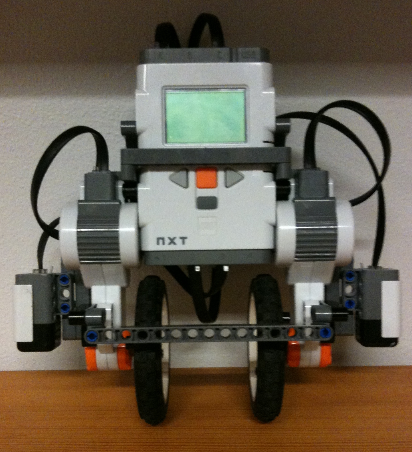
Figure 2 - The robot with accelerometer and gyro sensor

3. Accelerometer experiments
We used the lejos.nxt.addon.TiltSensor [2] class for reading sensor values. It is possible to get two values for each axis:
  • getTilt() - gets the tilt value where 200 corresponds to 1g
  • getAcceleration() - acceleration measured in mg (g = acceleration due to gravity = 9.81 m/s^2)
We wanted to monitor the accelerometer values, so we decided to send the accelerometer values to the PC via the Bluetooth framework developed in the last session.
Initially we wrote a test-program to get an idea of how the accelerometer worked and how it would react. Besides this we found out that it was a good idea to use one axis (X) to measure the acceleration, and another axis (Y) to measure the direction of this acceleration. This was because the values of the changes of the X-axis had the same sign indifferent of which direction the accelerometer was turned in. The Y-axis on the other hand went into overflow around the balancing point, allowing us to use this as an indicator of the direction the robot was toppling over. Unfortunately we did not get a graph of this, but with some willingness it is possible to get a notion of this behaviour in Figure 3, where the red graph is the X-axis, the yellow graph is the Y-axis, and the green graph is the combined data.

Figure 3 - Accelerometer readings: 
red: x-axis tilt
 yellow: y-axis tilt
 green: derived x-axis tilt

When we integrated the accelerometer in the main code, we ran into a problem where spikes in the readings occurred as seen below on Figure 4 (red+green):
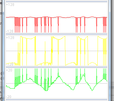
Figure 4 - Accelerometer readings: 
red: x-axis tilt
 yellow: y-axis tilt
 green: derived x-axis tilt

We found out that the reason for the spikes were that our regulation thread and Bluetooth thread read the sensor simultaneously. We solved this by adding a façade class to the accelerometer sensor, and thereby making a centralized access the accelerometer.

4. Combining  accelerometer and gyro sensor
There are not a lot of leJOS projects combining accelerometer and gyro values on the internet, but we found one, which is done by a guy named Andy Shaw. He has implemented a leJOS balancing robot [3] by using a homebuilt accelerometer and the gyro sensor from HiTechnic. The code is rather complex because it uses a Kalman filter [4] for joining the values from the accelerometer and the gyro and thereby eliminating the drift from the gyro. Because of the level of complexity we decided to leave the project for later experiments and try an alternate, and simpler, approach.

Our strategy is to use the gyro sensor for regulation and accelerometer for observing if the robot has reached the set point. So when the set point is reached the gyro angle is set to 0 to eliminate the drift.
Initially we used the method TiltSensor.getTilt() to read the state of the accelerometer. After some experiments we found that the data returned from getTilt() was too coarse-grained, meaning that the accelerometer would suggest that the robot was at set point in too big of an area around this point. Realizing this we used the method TiltSensor.getAccel() instead. This method returned data with a higher resolution than getTilt(), which decreased the area in which the accelerometer suggested set point. This, however, introduced a different problem to the accelerometer readings; fluctuating output.

In order to cancel out the noise in the accelerometer we implemented a running average mechanism. After experimenting with different ranges of values we concluded that it made the robot too unresponsive so we needed another strategy to handle the accelerometer properly.


5. Code refactoring
When we ran the program based on the code by Anette et al. we actually got a worse performance than in Session 2. We found out that the source of error originated in the program structure. We had a number of seven threads running including Bluetooth communication so we decided to simplify our architecture by decreasing the number of threads to two. The resulting architecture is illustrated on Figure 5. 


Figure 5 - UML class diagram showing the new and improved architecture


When designing the architecture, alternative architectures were considered. One possibility was a subsumption architecture [5,7] where there is a single thread for each behaviour and thereby a decentralized sensing. This solution was not chosen because our goal wasn't to support different behaviours, furthermore the different behaviours combined with Bluetooth communication can be as CPU intensive that it makes balancing impossible [5]. 

Conclusion:
The new architecture caused a better performance but we still had problems telling the robot when it is upright because of the performance of accelerometerAfter doing experiments with the accelerometer and the built-in leJOS class TiltSensor, we can conclude that the getTilt() method is too inaccurate to measure exactly if the robot is upright. The getAccel() method has contrary to getTilt() a relatively high resolution, but the high resolution reveals the oscillation in the accelerometer. The noise in the accelerometer has caused a lot of experiments ranging from a simple running average to home made filters. All of those failed and clearly showed that the accelerometer isn't capable of balancing the robot without assistance from another sensor.

The code for this session is found here: NXT [8] and PC [9].

References:
[3] Andy Shaw, Lego projects - http://www.gloomy-place.com/legoindex.htm
[4] Wikipedia, Kalman filter - http://en.wikipedia.org/wiki/Kalman_filter
[5] Rodney Brooks, A robust layered control system for a mobile robot, IEEE Journal of Robotics and Automation, RA-2(1):14-23, 1986
[6] Marvin Project, Lab report 5 - Bluetooth controlled robot -  http://wiki.aasimon.org/doku.php?id=marvin:ecp5
[7] Subsumption Architecture, Wikipedia - http://en.wikipedia.org/wiki/Subsumption_architecture
[8] L., Rasmussen, F., Laulund & C., Jensen, Session 2 source code on NXT, http://dl.dropbox.com/u/2389829/Lego/Session%203/Session%203%20NXT%20source%20code.zip
[9] L., Rasmussen, F., Laulund & C., Jensen, Session 2 source code on PC, http://dl.dropbox.com/u/2389829/Lego/Session%203/Session%203%20PC%20source%20code.zip

Thursday, December 9, 2010

Project Session 2

Date:
9/12 2010

Duration of activity:
7.5 hours

Group members participating:
Frederik, Christian & Lasse

Goals:
A. Allow for runtime adjustment of robot parameters such as PID-values, and to collect data/feedback from the robot.
B. Download the code from the Marvin-project to the robot, and make the necessary adjustments in order to make the robot balance.

Plan:
1. Acquire yet another NXT brick, and install leJOS on it.
2. Examine and prepare the Marvin-project to be downloaded to the robot (goal B).
3. Establish Bluetooth connection between NXT brick and computer (goal A).
4. Implement PC application with GUI for runtime adjustment of parameters and presentation of robot vitals (goal A),

Results:

1. Acquire another NXT
We were able to borrow another NXT brick from the library at the Engineering College of Aarhus. The brick contained original Lego firmware, so we uploaded the leJOS firmware to brick to be able to upload leJOS programs. This made it possible for us to work more efficiently when dealing with simultaneous tasks.

2. The Marvin project
We discovered that the Marvin group used version 0.8 of leJOS [3] because in version 0.85, which we use, the method getActualSpeed() in the Motor class no longer exists. This was a problem because we couldn't run their program without modifying their code. We replaced getActualSpeed() with getSpeed() because the documentation had similar descriptions for both methods. When running their code we received fault values for both motor power and the gyro sensor which kept rising. We therefore decided to ignore the tacho counter in their code to eliminate potential motor errors concerning the replacement of getActualSpeed() and instead focus on the gyro sensor. We modified their GyroscopeSensor class to use an ADSensorPort instead of SensorPort and added a call to the method setTypeAndMode() and we saw more promising results from the gyro sensor:


To make sure the different versions were not the main source of error we rolled back to version 0.8. This caused some trouble for Eclipse and we were not allowed to upload any programs, our theory is incompatibility between firmware versions. After having no luck with different firmware versions we decided to give up the experiments with Marvin and instead focus on the project done by Annette et al. in hope that they used version 0.85 of leJOS. 

The Annette project
To be able to balance the robot with the code from Annette et al. we needed to have a Bluetooth connection running between the NXT and a PC. We modified their code so we didn't have to use Bluetooth just to test their algorithm. Besides that we modified the project with the two classes, NewGyroSensor [4] and GyroSejway [5], which fitted our needs better. We tweaked the parameters of these classes to observe the effect of the different parameters. We merged the running average on the offset from Marvin with our existing gyro class but we only noticed a slight performance improvement. This ended up being the final result for this session - code is found in the classes NewGyroSensor and GyroSejway.

A video of the final result of the day can be seen below:

Video 1 - Final result

3. Bluetooth connection
To be able to adjust parameters for use in robot logic, we want to implement a PC application that via Bluetooth can send and receive data to/from the NXT-brick. Ideally the robot should connect to the PC on start up, hereby acting as master in the communication. This would mean that we did not need to initiate the connection via the PC application but merely wait for connection from NXT. Via the leJOS API it should be possible to initiate a connection from the NXT brick via the static functions of the Bluetooth-Class:

Unfortunately the NXT brick is not able to act as master in a Bluetooth communication. We were not even able to pair the NXT and the PC manually via the leJOS menu on the NXT. Maybe this was a problem with our specific brick or the PC we tried to connect to. Though by trying to manually pair the newly acquired NXT brick, we got the same result - unsuccessful. Also the PC we tried to connect to, was the same as we (via Bluetooth) load code onto the NXT from.

We decided not to go any further with this problem, and accept that the connection must be established from the PC-side, and thereby requiring our attention on connection (click). The NXT will then act as slave and wait for connection from the PC upon start.

The NXT part of the connection is implemented as follows:


Another array of problems was presented to us in this process, since leJOS does not allow a class to be named "BluetoothConnection", as this is a reserved name. Also "BTConnection" is a reserved class name. This was very unfortunate as these two exact names was the first two names we used for our class. This lead to quite a bit of confusion since the error-messages were not self-explanatory.

Also in order to use Bluetooth on NXT, the 3rd party leJOS library "bluecove" had to be included in the project build path. Bluecove can be located in the leJOS NXJ subfolders.

The data reception/sending is implemented in a single thread with reception as highest priority. This means that data will only be sent if there is no data ready to be read on the connection.


The sleep between each run of the Bluetooth thread logic must be determined with regard to load on NXT calculation power. The Bluetooth connection should not compromise the main functionality of the robot. This will be a matter that we must pay attention to on a later occasion.

4. PC application
Since the NXT was not able to act as master in the Bluetooth connection, the PC application had to have a connection button which initiates the Bluetooth connection. As soon as the connection is established, values for the calibration parameters in the robot logic can be entered, and sent via the GUI.


In order to monitor the sensor values and vitals (ex. calculated regulation power) of the robot, the PC application constantly waits for data from the Bluetooth connection. We considered whether these values should be saved and stored in a file for later investigation. But the best feature for us, would be a mean of live monitoring of sensor values and robot vitals. Therefore we wanted to present the received values in a graph, with the appearance of an EKG and its likes.

Since there is no standard implementation of a such in the java.awt [6] or Swing [7] we decided to implement this on our own. We implemented a class CustomGraph [8] that stores values in a circular buffer (also self-implemented) in order to store the same amount of values all the time. With every update of the CustomGraph, the values are read from the buffer, and each measurement is presented as a line drawn via the Graphics.drawLine() function. The CustomGraph class had to extend the JPanel in order to allow for Graphics manipulation.


Video 2 shows the result of the GUI application:

Video 2 - GUI application
 
Conclusion:
Getting the sample code running was way more difficult than expected because of differences in leJOS API and firmware versions. This caused us not to use the Marvin project as a starting point and instead using the project done by Annette et al.
With this software loaded on to the robot it was possible to see that the robot attempted to balance. It was, however, not fully up to the task - although it was pretty close. Some of the trouble with getting it to balance was due to difficulties in calibrating the robot, but the main trouble was with drifting of the gyro. During some of the longer balancing sessions, it was possible to see how the gyrometer suffered from drift, as the robot began to tilt, as time moved on.

We experienced that the gyrometer is quite sensitive to blows. By tapping the robot either in the front or in the back, it was possible to counteract the drifting a bit. The harder the blow or the closer to the gyrometer the "impact" occurs, the bigger the influence. A bit of a tedious method for eliminating drift, but it is a nice thing to know.

The PC application and the Bluetooth communication has been implemented and works as intended. It is possible to send PID and scale values to the robot and receive sensor values and robot vitals from the robot. By implementing the graph and thereby showing the received data from the robot runtime we should be able to better select the correct values for the PID calculation. This will be a good tool for our experimentation with other balancing methods in future sessions.

The code for this session is found here: NXT [9] and PC [10].

References:
[1] Johnny Rieper et al., "Marvin NXT", http://wiki.aasimon.org/doku.php?id=marvin:marvin
[2] Annette et al., "Balancing robot", http://annettesamuelrasmus.blogspot.com/
[3] leJOS version overview, http://sourceforge.net/projects/lejos/files/lejos-NXJ-win32/
[4] NewGyroSensor Java class, http://dl.dropbox.com/u/2389829/Lego/Session%202/NewGyroSensor.java
[5] GyroSejway Java class, http://dl.dropbox.com/u/2389829/Lego/Session%202/GyroSejway.java
[6] Java AWT - http://java.sun.com/products/jdk/awt/
[7] Java Swing - http://java.sun.com/products/jfc/tsc/articles/architecture/
[8] CustomGraph Java class, http://dl.dropbox.com/u/2389829/Lego/Session%202/CustomGraph.java
[9] L., Rasmussen, F., Laulund & C., Jensen, Session 2 source code on NXT, http://dl.dropbox.com/u/2678729/Lego/code/Session%202%20NXT%20source%20code.zip
[10] L., Rasmussen, F., Laulund & C., Jensen, Session 2 source code on PC, http://dl.dropbox.com/u/2678729/Lego/code/Session%202%20PC%20source%20code.zip

Thursday, December 2, 2010

Project Session 1

Date:
2/12 2010

Duration of activity:
6 hours

Group members participating:
Frederik, Christian & Lasse

Goals:
To determine which sensors to use in the project by investigating available sensors and previous projects experience with these.

Plan:
1. Investigate available sensors
2. Investigate earlier projects experience with different sensors for balancing a robot.
3. Construct the physical platform for a balancing robot.
4. Consider control strategy

Results:
1. Available sensors
The most obvious sensors to use for monitoring if the robot is balancing are:
- Accelerometer (or tilt sensor)
- Gyrometer
- Light sensor
- EOPD sensor

The difference in how these sensors work are:
- Accelerometer: Measures the acceleration along an axis (one or more, depending on the accelerometer type). This includes gravitational acceleration.
- Gyrometer: Measures rotation speed along an axis.
- Light sensor: Measures intensity of light.
- EOPD: The same as the light sensor but more advanced.

According to the leJOS documentation [6] all of these sensors are supported by the leJOS API if you stick with the brand HiTechnic. The GyroSensor class, however, is untested according to the documentation.

According to a post on the mindsensors.com forum [7] the processing speed of the NXT is not fast enough to use just the accelerometer. This might be because the mathematics required for obtaining the required data from just the accelerometer is quite complex. Here the gyrometer is recommended for balancing a robot.

We have previously used a light sensor for balancing a robot [8]. Our experience with this is that the sensor is very influenced by the ambient lighting conditions in the environment. Besides that, the sensor readings are also afftected by the texture and color of the reflecting surface. This makes it difficult to utilize the sensor for a balancing robot, if the surface does not have a consistent texture, and color.

The EOPD sensor is somewhat more advanced than the regular light sensor, as the sensor is immune to changes in the ambient lighting [9]. The issues with the reflecting surface, however, are the same as the regular light sensor.

The EOPD sensor could be used as a sensor for detecting if the robot is on the ground, or if the robot has fallen. This information could be used for e.g. stopping the motors when the robot has been lifted off of the ground, or deploying some sort of strategy for getting the robot back in action.

2. Earlier projects
This section describes the observations we have done by reading the lab reports of earlier projects.

2a. Annette et al. [1]
Annette et al. had the initial goal of making a robot balance through the Alishan track. They chose to use the gyro sensor for balancing which caused a lot of problems because of the drift in the sensor. The project goal changed to only focus on the drifting problem which they never managed to solve. They have some observations, though, that we can benefit from. For example they had a theory that the gyro offset gets fairly stable after 5-8 minuter, but they didn't prove it for some reason. Furthermore they read from a source that the gyro sensor requires at least 10 seconds warm up time. They suggested future groups to measure and investigate the drift over a longer period of time, say 30 min.

2b. Marvin [2]
Annette et al. based some of their work on a balancing robot project done in an earlier semester called Marvin. Marvin used a running average on the offset to minimize the drifting problem but Annette et al. didn't try that out, so this approach is surely relevant for us. To improve the balancing algorithm the Marvin group also used the tacho counter for the motors along with the gyro sensor to determine if the robot is still.

2c. Sejway [3]
This project focused on developing a selfbalancing robot based on sensor readings from a high precision lightsensor "EOPD" and a gyrosensor - both from HiTechnic [4].

The EOPD sensor proved to be very precise at measuring distances <5cm. Therefore an installation of the sensor must be close to the surface to ensure precise readings. The sensor output values are not absolute on different surfaces, but are not affected by ambient light. This means that when used on a flat, plain and single-color surface, the EOPD sensor output will be sufficient for determining robot angle. In a fall-test comparison of sensor output from gyro and EOPD, the EOPD sensor proved to react faster than gyro, hence producing more outputs pr. second.

The gyro sensor outputs values as degrees/second. The sensor values has an offset that's individual to each sensor, and some software calibration is therefore needed when installing a new sensor.

The regulation method used for this project was a PID-controller. The PID-values were hard for the group to determine, as they fairly late in the process managed to produce a proper robot design.

The physical construction of the robot turned out to be the determining factor of the project. They concluded that it was alpha and omega to have a robot design that is "ment for a balancing robot". Their solution was to create a weight-mechanism consisting of two large wheels on a lever. These weights could then be shifted on the lever in order to change the center of gravity.

3. Construction of robot
We found a physical design for a balancing robot made by Yorihisa Yamamoto [5]. As we didn't want to reinvent a robot, and as Y. Yamamoto had made this design work, we decided to use his construction as a base for our balancing robot.

We modified his design to fit our own needs - i.e. omitting unnecessary sensors, and slight construction changes for the sensor fitting.

A block diagram showing the final composition of the robot is shown on Figure 1. Note that even though the accelerometer is shown on the diagram, it wasn't mounted in this session.
Figure 1 - Composition of the balancing robot
The balancing robot acts as an inverted pendulum [10] - more specific as a the type cart and pole. Briefly explained, an inverted pendulum is like a regular pendulum, but with its mass above its pivot point. This of course makes the construction inherently unstable, and must be constantly corrected to keep the balance.
In our case the balancing will be done by continuously regulating the horizontal position of the pivot point by applying momentum to the wheels. This will make sure that the pivot point is (more or less*) directly under the centre of gravity. This will be part of a feedback system, which will be described at a later session.

*depending on our succes with the balancing act.

The resulting construction can be seen on Figures 2 and 3.
Figure 2 - The balancing robot construction (front)

Figure 3 - Rear view of the robot with the gyro sensor mounted

4. Considerations about control strategy
The way we intend to make the robot balance is by employing a feedback system using reactive control [11]. When the system detects that the robot is losing its balance (stimulus) via the sensor input, it will react by turning the wheels in one or the other direction - counteracting the loss of balance, and hopefully regain control.
The concept of this is depicted on Figure 4.

Figure 4 - Concept of stimulus-response system

The concept of this is that the system gets stimuli on the current situation from the environment via the sensors. Based on this information, the system will make a response, which in turn will "update" the environment, and new stimuli will be sensed.

Ideally this continuous stimulus-response loop will maintain status quo for our system, and - hopefully - make our robot balance.

Conclusion:
We found out that previous balancing robot projects all had problems with the drift in the gyro sensor and put a lot of work into getting it to behave satisfactory. We have decided that we won't make another balancing robot project with main focus on the gyro sensor. Instead we want to investigate alternative methods both by means of different sensors and regulation methods.
The derived value from the gyrometer should be the same value as an accelerometer would output, but since no earlier project has experimented with theese, we would like to see if the accelerometer yields better results than the derived gyro value.

A gyro sensor was available at the Lego Lab. We ordered two accelerometers at HiTechnic [4]. This means that we have to wait approximately a week until we can do experiments with the sensor
The EOPD sensor and lightsensors in general are limited to work on even, plane, single-color surface and will therefore only work in a controlled environment which requires a large amount of calibration before use. Even though the EOPD sensor is not influenced by ambient light, it still reacts different to color and texture. We would like to avoid this and has therefore chosen not to use the EOPD sensor.

We wanted to base the construction of the Lego robot on an existing design that has proven to be successful. Yorihisa Yamamoto [5] has constructed and implemented a robust balancing robot and even made a thorough construction manual, so we chose his design. The design is seen on Figure 1 and 2.

Based on previous experience gained in the lab sessions we wanted to make it easier to debug and change parameters runtime. The idea is to have the robot reporting state to a PC application and the PC application shall also be capable of sending values to the robot and thereby change control parameters runtime.


The code for this session is found here [12].

References:
[1] Annette et al., "Balancing robot", http://annettesamuelrasmus.blogspot.com/
[2] Johnny Rieper et al., "Marvin - project report 3", http://wiki.aasimon.org/doku.php?id=marvin:ecp3
[3] Sejway. Rasmus Gude et al. http://lego.secretman.dk/wiki
[4] HiTechnic http://www.hitechnic.com/
[5] Yorihisa Yamamoto, "NXTway-GS Building Instructions", http://dl.dropbox.com/u/2389829/Lego/Session%201/NXTway-GS%20Building%20Instructions.pdf
[6] leJOS NXJ API documentation, http://lejos.sourceforge.net/nxt/nxj/api/index.html
[7] mindsensors.com forums, "ACCEL sensor programming in NXT-G", http://www.mindsensors.com/forums/viewtopic.php?f=5&t=48
[8] Lego-lab 4, Christian Jensen, Frederik Laulund, Lasse H. Rasmussen, http://chrfredelasse.blogspot.com/2010/09/lab-exercise-4.html
[9] HiTechnic Blog, "EOPD – How to measure distance", http://www.hitechnic.com/blog/eopd-sensor/eopd-how-to-measure-distance/
[10] Inverted pendulum, Wikipedia, http://en.wikipedia.org/wiki/Inverted_pendulum
[11] Fred G. Martin, Robotic Explorations: A Hands-On Introduction to Engineering, Prentice Hall, 2001, Ch. 5: "Control"
[12] L., Rasmussen, F., Laulund & C., Jensen, Session 1 source code, http://dl.dropbox.com/u/2389829/Lego/Session%201/Sesssion%201%20source%20code.zip