Date:
03/01 2011
Duration of activity:
5 hours
Group members participating:
Frederik, Christian & Lasse
Goals:
Get the robot to be more responsive to changes in angle and hopefully make it balance satisfactory
Plan:
1. Do experiments with the adjustable values for complementary filter and PID controller [5]
2. Optimize the control loop to make the robot more responsive
3. Experiment with replacing the current PID controller with a PD controller
4. Investigate the use of small angle approximation
2. Optimize the control loop to make the robot more responsive
3. Experiment with replacing the current PID controller with a PD controller
4. Investigate the use of small angle approximation
Results:
1. Adjusting regulation values
Last session we concluded that the response time was way too slow to be able to balance the robot. We thought the source of error was the filter values used in the high- and and low pass filters but it showed not to be the main problem.
After observing the results from the previous session via the PC application, we noticed that the accelerometer angle and the gyro angular velocity were opposite. The reason for this, was that the gyro sensor and accelerometer are placed on opposite sites of the robot hence having opposite understanding of direction. The solution was simply to invert the gyro velocity value which resulted in the values for accelerometer and gyro now being in synch as seen on Figure 1.
Figure 1 - Shows that the gyro velocity interpretation (yellow) is now synchronized with the calculated angle from accelerometer (red). The response is now way faster(green)
In order to find the optimal values for the constants P, I and D in the regulation logic, we used the manual callibration approach [4,6]. By using the PC application we were able to change the constants live, hence seeing the effects immediately. First the P was incremented until a point where the robot was oscillating around the point of balance. This effect was accomplished at ~30. Next the I was callibrated by halfing P and incrementing I stepwise. At ~3 the effect of I meant that the robot was able to find a "sweet" spot at where it was standing perfectly still - as opposed to oscillating. The calibration of D was the same approach and should have the effect that the robot would respond rapidly to ex. touching/pusing.
We found that the optimal values for the PID constants was P = 13, I = 3.3, D = 3.7.
Motor effect:
We noticed that much of the time when the robot was balancing, the motors made a squeaking sound even when not turning the wheels. We found that this was due to a minimum motor power (at power = 5) at which the wheels was turning. This could recommend the use of a constant minimum power of 5 applied to the motors, where the regulation could control the remaining 95. But we decided not to implement this, since the minimum value are so low.
Motor difference:
When balancing the regulation of the wheels are not always equal on both motors. This causes the robot to rotate, when one motor is effected more than the other. This has no direct negative effect on the regulation itself other than the imperfect look of the robot movement, which is not directly forward and backwards as one would expect. We tried using different combinations of motor ports as we know that this had an effect in previous lab sessions. But the result remained the same.
A solution for this imperfection would be to use the tacho-counter to keep track of motor difference and thereby wheel movement. When one motor is behind on the tacho count this could be corrected for by effecting this motor more. This was the solution used in the Marvin project [1], and it now occured to us what the meaning of the tacho-part of the Marvin code that we, until now, had not fully understood.
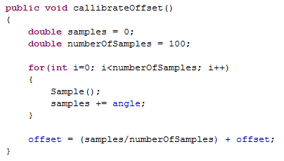
Accelerometer setpoint:
Because of the physical construction of the robot, the accelerometer reading at balance position are not ~0. This means that an offset had to be callibrated in order to get readings at ~0 when in balancing position. We decided to hardcode the offset as the offset should be constant.
The callibration had to be done manually by holding the robot in balancing position and reading from the accelerometer over an interval of time. The holding of the robot meant that it is not possible to hold it perfectly still and therefor it became somewhat of a trial and error approach. Some of the results are seen below:
Offset 3.707 - robot drives a bit forward.
Offset 3.9 - robot drives a bit backwards.
Offset 3.8 - acceptable behaviour.
Complementary filter optimization:
With the implementation of a complementary filter we were able to "trust" the gyro and accelerometer readings respectively. So we wanted to find a perfect combination of the values where the filter compensates for gyro drift and does not let the accelerometer noise affect the result.
Gyro: 0.98, Acc: 0.02 - Default values from last time.
Gyro: 0.90, Acc: 0.10 - Too affected by accelerometer noise.
Gyro: 0.99, Acc: 0.01 - Best result.
These values are callibrated with the regulation loop running in cycles of 25ms. If the loop cycle time is changed it will have an imediate effect on the filter result as the idea of the filter is to average over time. We therefore decided not to further change the cycle time of the regulation loop.
2. Optimizing of the control loop
2. Optimizing of the control loop
We earlier discovered that display outputs are a demanding task for the NXT. It should therefore always be a priority to limit the number of ouputs to a minimum. We therefore removed all outputs from the regulation loop, as these were only for debug use.
In order to make sure that the regulation loop is performed in constant intervals we used System.getSystemMilisecs(). With every regulation cycle a timestamp is saved and used post regulation to calculate the execution time of regulation. The sleep time can thereby be derived from the execution time and guarantee a constant regulation cycle interval.

The Bluetooth thread printed "sending" / "receiving" to the display in every cycle. It should be possible to limit the output, as it will rarely be receiving from the PC when running, hence printing "sending" with every run. We implemented a boolean flag to make sure that there is only printed to the display when state changes between sending/receiving.

3. PD controller
In the current PID controller, Integral error and Derivative error are derrived from proportional error (angle). An alternative to this solution is to use a PD controller [3], that uses the proportional error (angle) and the derivative angle from the gyrosensor. This should in theory yield the same result as proportional_error - last_proportional_error as the current controller is using. But since we have the derivative error factor expressed by the gyrosensors output (angular velocity), this would seem like an obvious choice. We decided not to use this method, but merely recognize it, as an alternative.
4. Small angle approximation
By doing some research online on the accelerometer angle calculation we discovered a method called small angle approximation [2] as illustrated on Figure 2. The reasoning behind using an alternative angle calculation is to limit the ressources needed for calculation. Our current trigonometric calculation is stated to be quite resource demanding whereas the small angle approximation should be able to do the same ange calculation with less resources - as long as angles are within -30 to 30 degrees.

Figure 2 - Small angle approximation. The value of the small angle X in radians is approximately equal to its tangent (Wikipedia)
By experimenting with both calculation and printing the calculation time required we observed that the small angle approximation was ~twice as fast as the trigonometric calculation. Although the time gained was only ~1ms we decided to use the small angle approximation as it is, none the less, faster.
Conclusion:
We are now able to present a balancing robot that is stable for more than a few seconds! The drift in the gyro and the noise in the accelerometer are both practically eliminated by using the complementary filter. The wheels are not in sync which makes the robot dance in circlular movements but this is not a critical error.
The optimization of the control loop ensures a fast and consistent regulation time which is an important factor when designing a fast response demanding system like ours.
There are still problems with balancing over longer periods of time. This may depend on both the gyro drift which are not totaly compensated for with our factors in the filter - but we expect it to be the offset of the accelerometer which may not be perfectly callibrated. And when moving over time the physical laws of lego makes the accelerometer shake out of place making the robot wander in one direction.
The implementation of the small angle approximation calculation is just as precise as the trigonometric calculation and at the same time less resource demanding. With the use of small angle approximation we are only able to read angles between -30 and 30 degrees. This has the side-effect that we are not able to read accelerometer values when robot is lying flat on table which could have been usefull for callibration. But the hardcoded value should be just as good.
The implementation of the small angle approximation calculation is just as precise as the trigonometric calculation and at the same time less resource demanding. With the use of small angle approximation we are only able to read angles between -30 and 30 degrees. This has the side-effect that we are not able to read accelerometer values when robot is lying flat on table which could have been usefull for callibration. But the hardcoded value should be just as good.
A video of the resulting balancing robot is seen below on Video 1. This shows that there is still room for improvements but is by far the best performance compared to the other sessions. The final code for the robot is found here: NXT [7] and PC [8].
Video 1 - The resulting and final video of the balancing robot.
References:
[1] Johnny Rieper et al., "Marvin NXT", http://wiki.aasimon.org/doku.php?id=marvin:marvin
[2] Small Angle Approximation, http://en.wikipedia.org/wiki/Small-angle_approximation
[3] PD Controller, Fred G. Martin, Robotic Explorations: A Hands-on Introduction to Engineering, Chapter 5, pp. 179-190, Prentice Hall, 2001.
[4] PID manual tuning, Wikipedia, http://en.wikipedia.org/wiki/PID_controller#Manual_tuning
[5] Vance J. VanDoren, Understanding PID Control, http://legolab.cs.au.dk/DigitalControl.dir/phys253lab5-PIDPrimer.pdf
[5] Vance J. VanDoren, Understanding PID Control, http://legolab.cs.au.dk/DigitalControl.dir/phys253lab5-PIDPrimer.pdf
[6] A PID Controller For Lego Mindstorms Robots, http://www.inpharmix.com/jps/PID_Controller_For_Lego_Mindstorms_Robots.html
[7] L., Rasmussen, F., Laulund & C., Jensen, Tilde final NXT code - Session 5, http://dl.dropbox.com/u/2389829/Lego/Session%205/Session%205%20NXT%20final%20source%20code.zip
[8] L., Rasmussen, F., Laulund & C., Jensen, Tilde final PC code - Session 5, http://dl.dropbox.com/u/2389829/Lego/Session%205/Session%205%20PC%20final%20source%20code.zip