Date:
07/01 2011
Duration of activity:
5½ hours
Group members participating:
Frederik, Christian & Lasse
Goals:
Do experiments with new physical regulation methods
Plan:
1. Construct a robot similar to the existing one, and mount a weight shifting device on top of it.
2. Do experiments with a new physical regulation method using weight shifting.
3. Construct a robot similar to the existing one, and mount an arm on top of it, acting as an inverted pendulum.
4. Do experiments with a new physical regulation method using an inverted pendulum.
3. Construct a robot similar to the existing one, and mount an arm on top of it, acting as an inverted pendulum.
4. Do experiments with a new physical regulation method using an inverted pendulum.
Results:
1. Construction of robot with mass displacement
The main idea of the new balancing method is to displace a mass back and forth to counteract if the robot is toppling over. This is illustrated on Figure 1.


In each end of the balancing stick we attached some mass in the form of several wheels.
As this device consisted of Lego Mindstorms parts for the structure, and some Lego Technic parts for the gear and rack, the cogwheel and the rack fitted very tightly. This was allieviated by using one of the long Mindstorms parts to build a sort of a slide. Unfortunately we didn't get any pictures of this little tweak.
The main idea of the new balancing method is to displace a mass back and forth to counteract if the robot is toppling over. This is illustrated on Figure 1.
Figure 1 - The new regulation method illustrated. A mass is placed across the robot, and displaced according to the current angle of the robot.
In order to displace the mass mounted on top of the robot it was necessary to construct a mechanism consitisting of gears, and a motor. This contraption is shown on Figure 2 and Figure 3.

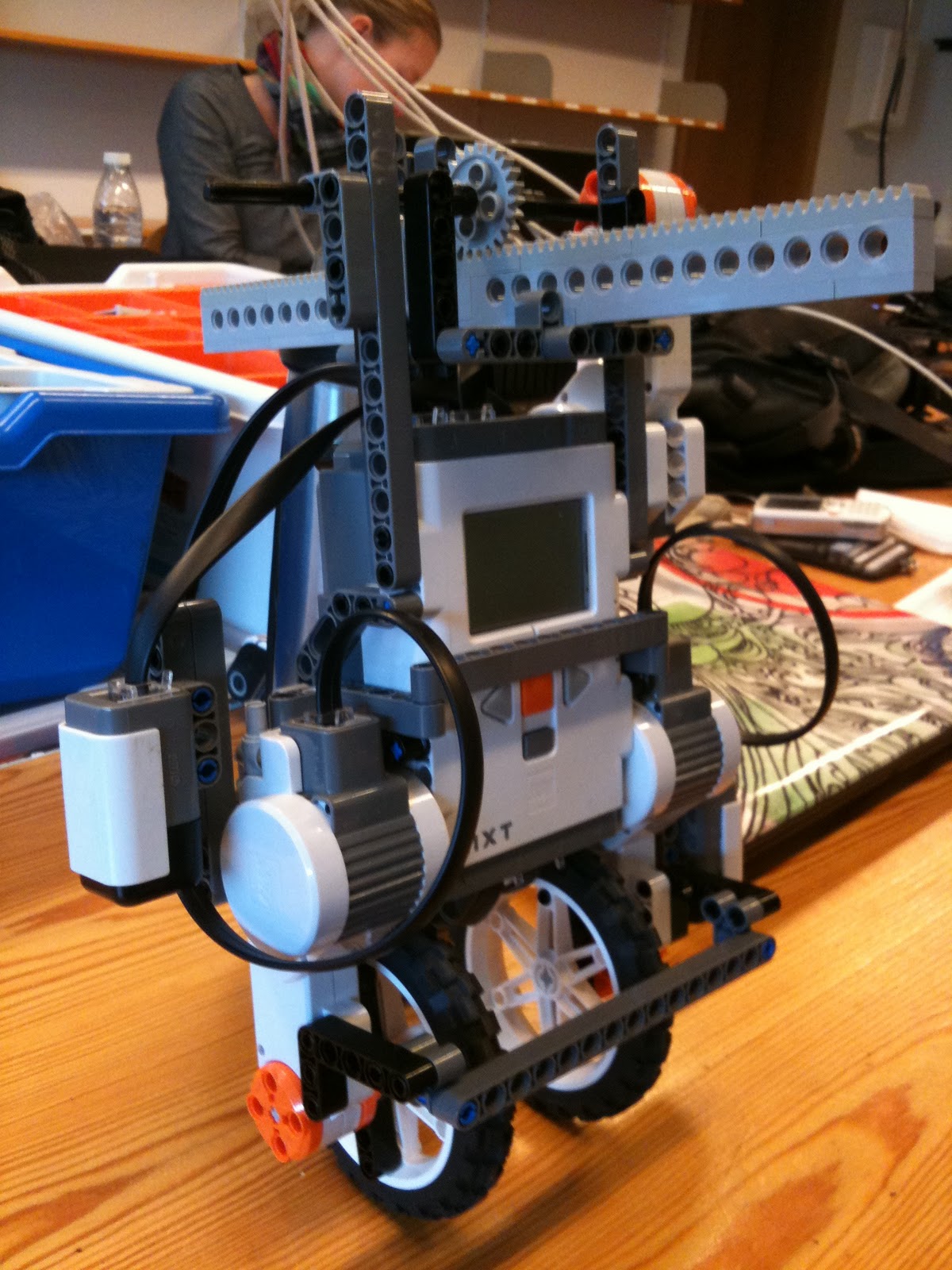
Figure 2 - Full view of the robot with the new balancing mechanism.

Figure 3 - Closeup of the weight shifting mechanism
In each end of the balancing stick we attached some mass in the form of several wheels.
As this device consisted of Lego Mindstorms parts for the structure, and some Lego Technic parts for the gear and rack, the cogwheel and the rack fitted very tightly. This was allieviated by using one of the long Mindstorms parts to build a sort of a slide. Unfortunately we didn't get any pictures of this little tweak.
2. Experiments with mass displacement
We tried using the well-known setPower()-method in the Motor-class for controlling the displacement. As with all physical changes to the robot, this required adjustments to the PID-values.
The downside to this method, however, was that we had no monitoring of travelled distance. This would be nice in order to control more easily where the mass should be shifted to.
Because of this we tried to use the rotateTo()-method in the Motor-class. This method uses the tacho-counter in order to give a perception of the distance the rack travels.
We found out, however, that this method takes much more time to use than setPower(). Our findings were that rotateTo() is about 10 times slower than setPower() (22 ms vs. ~200 ms).
Because of the increased time consumption of rotateTo() the sample rate of the sensors were now decreased. Because of this the class CumulativeSensor was made into a thread with the responsibilty to sample the accelerometer and gyrometer.
When dealing with displacement of af balancing stick, it is necessary to monitor/control that the stick isn't pushed beyond its endpoints. For this, rotateTo() was adjusted so that this would not happen.
The maximum travel length of the rack was set to 6.0 cm to each side.
The maximum travel length of the rack was set to 6.0 cm to each side.
The code - from the class Tilde [2] - below shows how, and with which value rotateTo() was used.
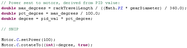
The motor power is set (in this example this is full power), and rotateTo() is called with the wanted degree-value.
We considered using the class TachoPilot but we chose not to, as we assessed that the advantage of this wasn't big enough. The advantage by using TachoPilot is that the travel distance can be set explicitly, but we still needed to do some "manual" calculations, which was why we opted this out.
We started out using a cogwheel with a diameter of 24 mm. In order to investigate if there was any improvement in the speed with which the mass was shifted, we tried with a bigger cogwheel (diameter 40 mm). As Video 1 shows, this didn't give any major improvements.Video 1 - Mass displacement regulation
After this we experimented with making the balancing stick longer as seen Figure 4. This didn't give any improvements on making the robot balance, as the reaction time wasn't fast enough.

Figure 4 - Longer balancing stick
Up until now the speed with which the mass was displaced depended on the angle of the robot, i.e. the bigger the angle, the faster the balancing stick should move.
To see if it would have any difference to just use max speed all the time, we set the speed with setPower(100). This didn't yield any improvement in form of the ability to balance.
We discovered that when the balancing stick was in one of the outer positions, it was not possible to recover if the robot's angle was more than a few degrees. We tried to improve this by adding more weight to the balancing stick, but this had little or no effect.
As a last attempt to get the mass displacement method to work, we tried an alternative construction. Instead of a stick with weights in both ends we tried to use a single weight. This construction is shown on Figure 5. Our thought was that this should be faster to regulate, as the stick shouldn't have to move as far as the model with two weights.
The result of this was that angle we could recover from was even smaller than before.

Figure 5 - Single weight
3. Construction of robot with inverted pendulum
The idea with the inverted pendulum [1] method is - like the mass displacement method - to counteract toppling by shifting the weight back or forth. The concept is shown on Figure 6.

Figure 6 - Concept of inverted pendulum construction

Figure 7 - Robot with inverted pendulum
4. Experiments with inverted pendulum
We tried this construction with both a long arm and a short arm on the pendulum to see if one would work better than the other. The results can be seen on videos 2 and 3.
Video 2 - Long arm inverted pendulum
Video 3 - Short arm inverted pendulum
As the videos show this wasn't the great succes either. It seems as though the long armed robot has the best preconditions for balancing, as it is better to salvage the robot than the small armed one.
Conclusion:
What we found from this experimental session is that it is much more difficult to make a robot balance using counterweights on the top than wheels at the bottom. The physics involved seems much more complex using these methods, and as software engineers we do not have the needed knowledge to sort this out.
Besides the complexity of the physics we found that rotateTo() isn't fast enough to use for this kind of balancing. The speed of the regulation isn't great enough to avoid the robot from falling.
Furthermore we made the balancing stick too limited in its travel length. We guess that if the balancing stick could have been pushed further out, that the robot would have a better chance to gain balance. This could possibly have been allieviated by mounting even more weight at the ends in order to balance and regulate properly.
As for the increase in the complexity of the involved physics, this was especially the case for the experiment with the inverted pendulum. This is because the robot itself acts as an inverted pendulum, and thereby we had to balance a pendulum with two pivot points, as shown on Figure 8.

Another issue with these balancing methods is that the torque produced by the motor on the balancing stick or pendulum is contributing to make the robot lose its balance - it pulls itself down when trying to regulate. It seems as if it's only when the weight has shifted fully either back or forth, that the robot gets "pulled" in the right direction by the momentum of the mass.
We thought that some of these problems could be minimized by using an "active", regular pendulum for balancing, controlled by a motor - see Figure 9 for the concept.

With this method we would not have the problem of trying to balance two pendulums on top of eachother. Furthermore we would not have the issue with the two weights more or less "cancelling" eachother out. What problems could surface from the before mentioned issue with torque pulling the robot down we cannot say, as we unfortunateliy did not have time for this experiment.
The code for this session is found here: NXT [3] and PC [4].
What we found from this experimental session is that it is much more difficult to make a robot balance using counterweights on the top than wheels at the bottom. The physics involved seems much more complex using these methods, and as software engineers we do not have the needed knowledge to sort this out.
Besides the complexity of the physics we found that rotateTo() isn't fast enough to use for this kind of balancing. The speed of the regulation isn't great enough to avoid the robot from falling.
Furthermore we made the balancing stick too limited in its travel length. We guess that if the balancing stick could have been pushed further out, that the robot would have a better chance to gain balance. This could possibly have been allieviated by mounting even more weight at the ends in order to balance and regulate properly.
As for the increase in the complexity of the involved physics, this was especially the case for the experiment with the inverted pendulum. This is because the robot itself acts as an inverted pendulum, and thereby we had to balance a pendulum with two pivot points, as shown on Figure 8.
Figure 8 - Pivot points of the double inverted pendulum
Another issue with these balancing methods is that the torque produced by the motor on the balancing stick or pendulum is contributing to make the robot lose its balance - it pulls itself down when trying to regulate. It seems as if it's only when the weight has shifted fully either back or forth, that the robot gets "pulled" in the right direction by the momentum of the mass.
We thought that some of these problems could be minimized by using an "active", regular pendulum for balancing, controlled by a motor - see Figure 9 for the concept.
Figure 9 - Regular pendulum
With this method we would not have the problem of trying to balance two pendulums on top of eachother. Furthermore we would not have the issue with the two weights more or less "cancelling" eachother out. What problems could surface from the before mentioned issue with torque pulling the robot down we cannot say, as we unfortunateliy did not have time for this experiment.
The code for this session is found here: NXT [3] and PC [4].
References:
[1] Inverted pendulum, Wikipedia, http://en.wikipedia.org/wiki/Inverted_pendulum
[2] Tilde class, session 6, http://dl.dropbox.com/u/2678729/Lego/P_session6/Tilde.java
[3] L., Rasmussen, F., Laulund & C., Jensen, Session 2 source code on NXT, http://dl.dropbox.com/u/2678729/Lego/code/Session%206%20NXT%20source%20code.zip
[4] L., Rasmussen, F., Laulund & C., Jensen, Session 2 source code on PC, http://dl.dropbox.com/u/2678729/Lego/code/Session%206%20PC%20source%20code.zip