Thursday, December 9, 2010

Project Session 2

Date:
9/12 2010

Duration of activity:
7.5 hours

Group members participating:
Frederik, Christian & Lasse

Goals:
A. Allow for runtime adjustment of robot parameters such as PID-values, and to collect data/feedback from the robot.
B. Download the code from the Marvin-project to the robot, and make the necessary adjustments in order to make the robot balance.

Plan:
1. Acquire yet another NXT brick, and install leJOS on it.
2. Examine and prepare the Marvin-project to be downloaded to the robot (goal B).
3. Establish Bluetooth connection between NXT brick and computer (goal A).
4. Implement PC application with GUI for runtime adjustment of parameters and presentation of robot vitals (goal A),

Results:

1. Acquire another NXT
We were able to borrow another NXT brick from the library at the Engineering College of Aarhus. The brick contained original Lego firmware, so we uploaded the leJOS firmware to brick to be able to upload leJOS programs. This made it possible for us to work more efficiently when dealing with simultaneous tasks.

2. The Marvin project
We discovered that the Marvin group used version 0.8 of leJOS [3] because in version 0.85, which we use, the method getActualSpeed() in the Motor class no longer exists. This was a problem because we couldn't run their program without modifying their code. We replaced getActualSpeed() with getSpeed() because the documentation had similar descriptions for both methods. When running their code we received fault values for both motor power and the gyro sensor which kept rising. We therefore decided to ignore the tacho counter in their code to eliminate potential motor errors concerning the replacement of getActualSpeed() and instead focus on the gyro sensor. We modified their GyroscopeSensor class to use an ADSensorPort instead of SensorPort and added a call to the method setTypeAndMode() and we saw more promising results from the gyro sensor:


To make sure the different versions were not the main source of error we rolled back to version 0.8. This caused some trouble for Eclipse and we were not allowed to upload any programs, our theory is incompatibility between firmware versions. After having no luck with different firmware versions we decided to give up the experiments with Marvin and instead focus on the project done by Annette et al. in hope that they used version 0.85 of leJOS. 

The Annette project
To be able to balance the robot with the code from Annette et al. we needed to have a Bluetooth connection running between the NXT and a PC. We modified their code so we didn't have to use Bluetooth just to test their algorithm. Besides that we modified the project with the two classes, NewGyroSensor [4] and GyroSejway [5], which fitted our needs better. We tweaked the parameters of these classes to observe the effect of the different parameters. We merged the running average on the offset from Marvin with our existing gyro class but we only noticed a slight performance improvement. This ended up being the final result for this session - code is found in the classes NewGyroSensor and GyroSejway.

A video of the final result of the day can be seen below:

Video 1 - Final result

3. Bluetooth connection
To be able to adjust parameters for use in robot logic, we want to implement a PC application that via Bluetooth can send and receive data to/from the NXT-brick. Ideally the robot should connect to the PC on start up, hereby acting as master in the communication. This would mean that we did not need to initiate the connection via the PC application but merely wait for connection from NXT. Via the leJOS API it should be possible to initiate a connection from the NXT brick via the static functions of the Bluetooth-Class:

Unfortunately the NXT brick is not able to act as master in a Bluetooth communication. We were not even able to pair the NXT and the PC manually via the leJOS menu on the NXT. Maybe this was a problem with our specific brick or the PC we tried to connect to. Though by trying to manually pair the newly acquired NXT brick, we got the same result - unsuccessful. Also the PC we tried to connect to, was the same as we (via Bluetooth) load code onto the NXT from.

We decided not to go any further with this problem, and accept that the connection must be established from the PC-side, and thereby requiring our attention on connection (click). The NXT will then act as slave and wait for connection from the PC upon start.

The NXT part of the connection is implemented as follows:


Another array of problems was presented to us in this process, since leJOS does not allow a class to be named "BluetoothConnection", as this is a reserved name. Also "BTConnection" is a reserved class name. This was very unfortunate as these two exact names was the first two names we used for our class. This lead to quite a bit of confusion since the error-messages were not self-explanatory.

Also in order to use Bluetooth on NXT, the 3rd party leJOS library "bluecove" had to be included in the project build path. Bluecove can be located in the leJOS NXJ subfolders.

The data reception/sending is implemented in a single thread with reception as highest priority. This means that data will only be sent if there is no data ready to be read on the connection.


The sleep between each run of the Bluetooth thread logic must be determined with regard to load on NXT calculation power. The Bluetooth connection should not compromise the main functionality of the robot. This will be a matter that we must pay attention to on a later occasion.

4. PC application
Since the NXT was not able to act as master in the Bluetooth connection, the PC application had to have a connection button which initiates the Bluetooth connection. As soon as the connection is established, values for the calibration parameters in the robot logic can be entered, and sent via the GUI.


In order to monitor the sensor values and vitals (ex. calculated regulation power) of the robot, the PC application constantly waits for data from the Bluetooth connection. We considered whether these values should be saved and stored in a file for later investigation. But the best feature for us, would be a mean of live monitoring of sensor values and robot vitals. Therefore we wanted to present the received values in a graph, with the appearance of an EKG and its likes.

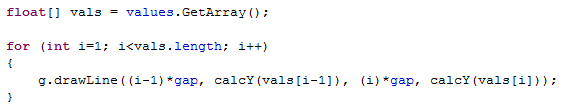
Since there is no standard implementation of a such in the java.awt [6] or Swing [7] we decided to implement this on our own. We implemented a class CustomGraph [8] that stores values in a circular buffer (also self-implemented) in order to store the same amount of values all the time. With every update of the CustomGraph, the values are read from the buffer, and each measurement is presented as a line drawn via the Graphics.drawLine() function. The CustomGraph class had to extend the JPanel in order to allow for Graphics manipulation.


Video 2 shows the result of the GUI application:

Video 2 - GUI application
 
Conclusion:
Getting the sample code running was way more difficult than expected because of differences in leJOS API and firmware versions. This caused us not to use the Marvin project as a starting point and instead using the project done by Annette et al.
With this software loaded on to the robot it was possible to see that the robot attempted to balance. It was, however, not fully up to the task - although it was pretty close. Some of the trouble with getting it to balance was due to difficulties in calibrating the robot, but the main trouble was with drifting of the gyro. During some of the longer balancing sessions, it was possible to see how the gyrometer suffered from drift, as the robot began to tilt, as time moved on.

We experienced that the gyrometer is quite sensitive to blows. By tapping the robot either in the front or in the back, it was possible to counteract the drifting a bit. The harder the blow or the closer to the gyrometer the "impact" occurs, the bigger the influence. A bit of a tedious method for eliminating drift, but it is a nice thing to know.

The PC application and the Bluetooth communication has been implemented and works as intended. It is possible to send PID and scale values to the robot and receive sensor values and robot vitals from the robot. By implementing the graph and thereby showing the received data from the robot runtime we should be able to better select the correct values for the PID calculation. This will be a good tool for our experimentation with other balancing methods in future sessions.

The code for this session is found here: NXT [9] and PC [10].

References:
[1] Johnny Rieper et al., "Marvin NXT", http://wiki.aasimon.org/doku.php?id=marvin:marvin
[2] Annette et al., "Balancing robot", http://annettesamuelrasmus.blogspot.com/
[3] leJOS version overview, http://sourceforge.net/projects/lejos/files/lejos-NXJ-win32/
[4] NewGyroSensor Java class, http://dl.dropbox.com/u/2389829/Lego/Session%202/NewGyroSensor.java
[5] GyroSejway Java class, http://dl.dropbox.com/u/2389829/Lego/Session%202/GyroSejway.java
[6] Java AWT - http://java.sun.com/products/jdk/awt/
[7] Java Swing - http://java.sun.com/products/jfc/tsc/articles/architecture/
[8] CustomGraph Java class, http://dl.dropbox.com/u/2389829/Lego/Session%202/CustomGraph.java
[9] L., Rasmussen, F., Laulund & C., Jensen, Session 2 source code on NXT, http://dl.dropbox.com/u/2678729/Lego/code/Session%202%20NXT%20source%20code.zip
[10] L., Rasmussen, F., Laulund & C., Jensen, Session 2 source code on PC, http://dl.dropbox.com/u/2678729/Lego/code/Session%202%20PC%20source%20code.zip

Thursday, December 2, 2010

Project Session 1

Date:
2/12 2010

Duration of activity:
6 hours

Group members participating:
Frederik, Christian & Lasse

Goals:
To determine which sensors to use in the project by investigating available sensors and previous projects experience with these.

Plan:
1. Investigate available sensors
2. Investigate earlier projects experience with different sensors for balancing a robot.
3. Construct the physical platform for a balancing robot.
4. Consider control strategy

Results:
1. Available sensors
The most obvious sensors to use for monitoring if the robot is balancing are:
- Accelerometer (or tilt sensor)
- Gyrometer
- Light sensor
- EOPD sensor

The difference in how these sensors work are:
- Accelerometer: Measures the acceleration along an axis (one or more, depending on the accelerometer type). This includes gravitational acceleration.
- Gyrometer: Measures rotation speed along an axis.
- Light sensor: Measures intensity of light.
- EOPD: The same as the light sensor but more advanced.

According to the leJOS documentation [6] all of these sensors are supported by the leJOS API if you stick with the brand HiTechnic. The GyroSensor class, however, is untested according to the documentation.

According to a post on the mindsensors.com forum [7] the processing speed of the NXT is not fast enough to use just the accelerometer. This might be because the mathematics required for obtaining the required data from just the accelerometer is quite complex. Here the gyrometer is recommended for balancing a robot.

We have previously used a light sensor for balancing a robot [8]. Our experience with this is that the sensor is very influenced by the ambient lighting conditions in the environment. Besides that, the sensor readings are also afftected by the texture and color of the reflecting surface. This makes it difficult to utilize the sensor for a balancing robot, if the surface does not have a consistent texture, and color.

The EOPD sensor is somewhat more advanced than the regular light sensor, as the sensor is immune to changes in the ambient lighting [9]. The issues with the reflecting surface, however, are the same as the regular light sensor.

The EOPD sensor could be used as a sensor for detecting if the robot is on the ground, or if the robot has fallen. This information could be used for e.g. stopping the motors when the robot has been lifted off of the ground, or deploying some sort of strategy for getting the robot back in action.

2. Earlier projects
This section describes the observations we have done by reading the lab reports of earlier projects.

2a. Annette et al. [1]
Annette et al. had the initial goal of making a robot balance through the Alishan track. They chose to use the gyro sensor for balancing which caused a lot of problems because of the drift in the sensor. The project goal changed to only focus on the drifting problem which they never managed to solve. They have some observations, though, that we can benefit from. For example they had a theory that the gyro offset gets fairly stable after 5-8 minuter, but they didn't prove it for some reason. Furthermore they read from a source that the gyro sensor requires at least 10 seconds warm up time. They suggested future groups to measure and investigate the drift over a longer period of time, say 30 min.

2b. Marvin [2]
Annette et al. based some of their work on a balancing robot project done in an earlier semester called Marvin. Marvin used a running average on the offset to minimize the drifting problem but Annette et al. didn't try that out, so this approach is surely relevant for us. To improve the balancing algorithm the Marvin group also used the tacho counter for the motors along with the gyro sensor to determine if the robot is still.

2c. Sejway [3]
This project focused on developing a selfbalancing robot based on sensor readings from a high precision lightsensor "EOPD" and a gyrosensor - both from HiTechnic [4].

The EOPD sensor proved to be very precise at measuring distances <5cm. Therefore an installation of the sensor must be close to the surface to ensure precise readings. The sensor output values are not absolute on different surfaces, but are not affected by ambient light. This means that when used on a flat, plain and single-color surface, the EOPD sensor output will be sufficient for determining robot angle. In a fall-test comparison of sensor output from gyro and EOPD, the EOPD sensor proved to react faster than gyro, hence producing more outputs pr. second.

The gyro sensor outputs values as degrees/second. The sensor values has an offset that's individual to each sensor, and some software calibration is therefore needed when installing a new sensor.

The regulation method used for this project was a PID-controller. The PID-values were hard for the group to determine, as they fairly late in the process managed to produce a proper robot design.

The physical construction of the robot turned out to be the determining factor of the project. They concluded that it was alpha and omega to have a robot design that is "ment for a balancing robot". Their solution was to create a weight-mechanism consisting of two large wheels on a lever. These weights could then be shifted on the lever in order to change the center of gravity.

3. Construction of robot
We found a physical design for a balancing robot made by Yorihisa Yamamoto [5]. As we didn't want to reinvent a robot, and as Y. Yamamoto had made this design work, we decided to use his construction as a base for our balancing robot.

We modified his design to fit our own needs - i.e. omitting unnecessary sensors, and slight construction changes for the sensor fitting.

A block diagram showing the final composition of the robot is shown on Figure 1. Note that even though the accelerometer is shown on the diagram, it wasn't mounted in this session.
Figure 1 - Composition of the balancing robot
The balancing robot acts as an inverted pendulum [10] - more specific as a the type cart and pole. Briefly explained, an inverted pendulum is like a regular pendulum, but with its mass above its pivot point. This of course makes the construction inherently unstable, and must be constantly corrected to keep the balance.
In our case the balancing will be done by continuously regulating the horizontal position of the pivot point by applying momentum to the wheels. This will make sure that the pivot point is (more or less*) directly under the centre of gravity. This will be part of a feedback system, which will be described at a later session.

*depending on our succes with the balancing act.

The resulting construction can be seen on Figures 2 and 3.
Figure 2 - The balancing robot construction (front)

Figure 3 - Rear view of the robot with the gyro sensor mounted

4. Considerations about control strategy
The way we intend to make the robot balance is by employing a feedback system using reactive control [11]. When the system detects that the robot is losing its balance (stimulus) via the sensor input, it will react by turning the wheels in one or the other direction - counteracting the loss of balance, and hopefully regain control.
The concept of this is depicted on Figure 4.

Figure 4 - Concept of stimulus-response system

The concept of this is that the system gets stimuli on the current situation from the environment via the sensors. Based on this information, the system will make a response, which in turn will "update" the environment, and new stimuli will be sensed.

Ideally this continuous stimulus-response loop will maintain status quo for our system, and - hopefully - make our robot balance.

Conclusion:
We found out that previous balancing robot projects all had problems with the drift in the gyro sensor and put a lot of work into getting it to behave satisfactory. We have decided that we won't make another balancing robot project with main focus on the gyro sensor. Instead we want to investigate alternative methods both by means of different sensors and regulation methods.
The derived value from the gyrometer should be the same value as an accelerometer would output, but since no earlier project has experimented with theese, we would like to see if the accelerometer yields better results than the derived gyro value.

A gyro sensor was available at the Lego Lab. We ordered two accelerometers at HiTechnic [4]. This means that we have to wait approximately a week until we can do experiments with the sensor
The EOPD sensor and lightsensors in general are limited to work on even, plane, single-color surface and will therefore only work in a controlled environment which requires a large amount of calibration before use. Even though the EOPD sensor is not influenced by ambient light, it still reacts different to color and texture. We would like to avoid this and has therefore chosen not to use the EOPD sensor.

We wanted to base the construction of the Lego robot on an existing design that has proven to be successful. Yorihisa Yamamoto [5] has constructed and implemented a robust balancing robot and even made a thorough construction manual, so we chose his design. The design is seen on Figure 1 and 2.

Based on previous experience gained in the lab sessions we wanted to make it easier to debug and change parameters runtime. The idea is to have the robot reporting state to a PC application and the PC application shall also be capable of sending values to the robot and thereby change control parameters runtime.


The code for this session is found here [12].

References:
[1] Annette et al., "Balancing robot", http://annettesamuelrasmus.blogspot.com/
[2] Johnny Rieper et al., "Marvin - project report 3", http://wiki.aasimon.org/doku.php?id=marvin:ecp3
[3] Sejway. Rasmus Gude et al. http://lego.secretman.dk/wiki
[4] HiTechnic http://www.hitechnic.com/
[5] Yorihisa Yamamoto, "NXTway-GS Building Instructions", http://dl.dropbox.com/u/2389829/Lego/Session%201/NXTway-GS%20Building%20Instructions.pdf
[6] leJOS NXJ API documentation, http://lejos.sourceforge.net/nxt/nxj/api/index.html
[7] mindsensors.com forums, "ACCEL sensor programming in NXT-G", http://www.mindsensors.com/forums/viewtopic.php?f=5&t=48
[8] Lego-lab 4, Christian Jensen, Frederik Laulund, Lasse H. Rasmussen, http://chrfredelasse.blogspot.com/2010/09/lab-exercise-4.html
[9] HiTechnic Blog, "EOPD – How to measure distance", http://www.hitechnic.com/blog/eopd-sensor/eopd-how-to-measure-distance/
[10] Inverted pendulum, Wikipedia, http://en.wikipedia.org/wiki/Inverted_pendulum
[11] Fred G. Martin, Robotic Explorations: A Hands-On Introduction to Engineering, Prentice Hall, 2001, Ch. 5: "Control"
[12] L., Rasmussen, F., Laulund & C., Jensen, Session 1 source code, http://dl.dropbox.com/u/2389829/Lego/Session%201/Sesssion%201%20source%20code.zip

Thursday, November 25, 2010

Project Session 0

Date:
25/11 2010

Duration of activity:
3 hours

Group members participating:
Frederik, Christian & Lasse

Goals:
Discuss and describe possible end course projects and end up having one selected

Plan:
Make a description of three possible end course projects containing a description, overall architecture and point out some potential problems.

Results:
After a discussion we came up with the three following projects:

1. A convoy of Lego cars acting as a train with a leader car in front
This would require the robot wagons to keep a fixed distance to the wagon ahead but also to follow its direction. Ultrasonic sensors could be used both to measure the distance but also to ensure that the wagon ahead is between two ultrasonic sensors. Experiments with other sensors such as cameras and light sensors could also be done. The leader car could be driving randomly around or be controlled by a joystick or a Wii remote via a PC.

A sketch of a possible system setup is seen on figure 1 below:
Figure 1 - Possible architecture of the Lego convoy project


The main challenge would be to keep the direction with the wagon ahead, though it should be possible to accomplish a three-wagon convoy controlled with a Wii remote (via Bluetooth) that maintains a fixed distance between the wagons and lets the lead wagon control the direction.


2. Balancing robot experiments
We would take the issues identified in previous lab sessions with balancing robots as a starting point and experiment with diferent ways of keeping balance. How effective would it be to regulate using a balancing stick instead of the motors? The main problem with our previous work with the balancing robot was the inaccuracy of the light sensor as a means of regulating balance. The alternative methods for balancing a robot could maybe complement the existing sejway motor-approach in a 2-axis balancing robot.

Figure 2 - Different regulation methods for maintaining balance. a) Regulating the wheels by motors b) Using a slider to change the balance c) Make a stick swing to change the balance.

The addition of a second axis will be a challenge and will require a lot of experimenting with different sensors and regulation methods. Another goal for this project could be to introduce another or several other sensor(s) to measure the attitude thereby limiting the inaccuracy of our previous attempts. The main goal for this project will be to have a balancing robot working with diferent methods for balancing. Best case scenario is a 2-axis balancing robot that is able to correct for falls in 2 axis.

3. Gene inheritance among a flock of robots
The idea is to have some robot parents each with a set of genes that can be mixed when they have a baby. The parents should then mate several times and have children with different behaviours based on the genes of the parents.

The transferring of genes can be handled by a server PC which distributes the genes to the parents and the parents then combine their genes which is sent to a "baby robot". The challenge in this project is to handle the level of complexity because the definition and exchange of genes can easily get complex when new genes are introduced. A subsumption architecture can be used to define the priority of the different behaviours for each robot - an example is shown below:


Figure 3 - Example of a set of genes and the matching behaviours

A sketch of a possible system setup can be seen on figure 4 below:

Figure 4 - A proposal for a system with a flock of mating robots with inherited genes


Conclusion:
We ended up choosing the Balancing robot experiments because we were interested in improving the robot from the lab sessions, but also to investigate whether it is possible to add an axis and still make the robot balance satisfactory. In the lab sessions light sensors were used but we will also try to combine with other sensors such as a gyroscope. Alternatives to motor regulation for balancing will also be investigated as shown on Figure 2. The construction of the robot will also have a lot to say, which will lead to experiments with the construction of the robot. Because similar projects have been done in the previous years there should be plenty of inspiration.

Lab Exercise 10

Date:
18/11 2010

Duration of activity:
3 hours

Group members participating:
Frederik, Christian & Lasse

Goals:
To investigate the leJOS API "subsumption" architecture by using a BumperCar-example as a starting point. 

Plan:
1. Get the sample running and observe the behaviour
2. Do experiments with the BumperCar sample code
3. Implement a new behaviour called Exit, which shall exit the program


Results:

1. Running the sample
We reused the construction of the car from the last lab session equipped with two motors. Furthermore we needed to mount a bump sensor and an ultrasonic sensor on the car because they are used by the DetectWall behaviour in the BumperCar sample. We though chose to mount two bump sensors to achive a better detection of bumps in front of the car. An image of the car is seen below:


When running the sample the overall behaviour was as expected; the car drives forward until an obstacle is detected by the ultra sonic sensor (within 25 cm) or the bump sensors, the car then backs of and rotates, and continues to drive forward. Before doing experiments with the sample code we decided to make it possible to exit the program when pressing the escape button - we just made as a thread listening for the button press, this was not the actual Exit behaviour implementation. This was done because the building structure of the car made it difficult the access the battery, which was necessary remove in order to exit the application (we later found out that a program can be terminated by pressing the enter and escape buttons simultaneously).

2. Experiments
When keeping the bump sensor pressed the DetectWall behaviour suppresses the DriveForward because the takeControl() method of DetectWall yields true when the bump sensor is pressed. When looking at the Arbitrator class it is seen that the list of behaviours is traversed and the highest index gets the highest priority and lower prioritized behaviours are supressed as seen below:


3. Exit behaviour
The escape code made in point 1 was removed to ensure that only the new Exit behaviour reacts to escape button presses. The exit behaviour was implemented with highest priority and when running the code we noticed that when the DetectWall behaviour has control the program is blocked i.e. it is not possible to poll the exit button until the rotation is finished. This is caused both by the Motor.A.rotate(-180, true); and Motor.C.rotate(-360); statements but the Sound.pause(20); statement also has a little influence. When increasing the Sound.pause parameter to 2000 ms a delay of 2 sec is added which causes the Arbitrator to block the takeControl() checks which is seen in the code example above.


The code for the exit behaviour is seen in the Exit class in the file BumperCar.java[1]


Because the DetectWall class is no longer the highest prioritized class we added some handling to its supress() method which stops the motors if they are running. We noticed that the action method of DetectWall had different behaviour for the two rotate-calls to the motors as seen below:
The true parameter is 'immediate return' which causes the method call to return right after it is called. This must not be done for the call to motor C because that would have caused that the action method returned right after it is called and thereby not getting enough time to back off.


To make the takeControl() in DetectWall more responsive we made a Thread which handles the reading of the sonar sensor and writes to a shared variable. This variable is then read by the takeControl() method and thereby avoiding the delay which previous was in the method, this is illustrated below:


To make sure that the routine stops if it is suppressed during the sleep period we made an action thread for DetectWall which performs the back off action; moves backwards for a second and then rotates. If the thread is interrupted during sleep (by a suppression) the thread returns and thereby ignores the rotation. This implementation sadly didn't work out because of some threading problems that we didn't manage to solve.

Conclusion:
We have seen that it is possible to improve the performance of a certain behaviour by moving the sampling of a particular sensor into a separate thread. This is because the sensor reading lasts a certain amount of time and thereby blocking the main program if the reading isn't performed in a separate thread. Generally a lot of tweaking can be done using the subsumption architecture by means of moving time consuming parts to threads and thereby making the program more responsive.


References:

Thursday, November 18, 2010

Lab Exercise 9

Date:
11/11 2010

Duration of activity:
3 hours

Group members participating:
Frederik, Christian & Lasse

Goals:
The main goal is to keep track of the position and direction (pose) of a Lego car by using the tacho counters. 

Plan:
1. Experiment with the SimpleNavigator class (instead of TachoNavigator which is deprecated)
2. Experiment with navigation while avoiding obstacles

Results:

1. Navigation

The first experiment was to make the car move to different positions and then return to the start position and thereby observe the accuracy. To get a better idea of the accuracy we mounted a whiteboard marker on the car and thereby made the car trace its own path on a whiteboard placed horizontally on the floor. The car with the marker mounted is seen below:


We made a route with 4 waypoints ending at the start point and saw an inaccuracy of approximately 10 cm as seen in the video below. As Brian Bagnall [1] also states the main source of error is the tacho rotation but wheel spin is also a source of error as we also experienced in the Lego race lab exercise. 


To avoid the wheel spin we experimented with a paper surface instead of the whiteboard. The idea behind using paper as surface was that we assumed 1) that the tyres would have better traction than on a slippery whiteboard, and 2) that the paper would easier slip on the surface of the whiteboard than under the tyres of the vehicle. We actually didn't notice a huge difference but when we tried to use the Reverse property in the TachoPillot constructor we got an even worse behaviour. We also noticed that the starting angle of the rear wheel has an impact of the result. So we concluded that performances on the two different surfaces were roughly the same.


2. Navigation with obstacle avoidance
We mounted the ultrasonic sensor on the Lego car to be able to detect obstacles in front of the car. The SimpleNavigator was investigated by means of its behaviour when a goTo()-action is aborted, because this will be the case when avoiding obstacles. We wanted to make the car continue when aborted in a goTo() action. We did this by creating a Thread to simulate the avoidance behaviour and thereby blocking the navigation thread. The navigator thread uses a flag to determine if the goTo()-action was finished or aborted, if aborted the command should be repeated. This principle was used for a set of positions where an obstacle was placed in the way of the path - this scenario can been on the video below:


The code is found in the class BlighbotExtended [2] and the avoidance is done in the method avoider():


The handling of the positions is done in the main thread where the flag as mentioned before is used to check for interruption: 


Conclusion:
When using the tacho counter we observed and measured that the distance travelled by using tacho count was very accurate but the rotation was not. To improve the rotation accuracy additional control of the motors is needed because the inaccuracy occurs because the motors "may not stop smoothly at the target angle if called when the motor is already moving" [3]. The implementation should be less fluent like our implementation for the Lego race[4] where the car stopped before each rotation.

As seen on the second video the vehicle is able to avoid an obstacle dynamically appearing in front of it. The chosen method for this avoidance is to let the vehicle stray a given distance to one side, when an obstacle is detected, and when finished this avoidance, recalculate the direction needed to obtain the original goal. This simple method has a problem if the next goal is too close the obstacle, because the obstacle could be in the path needed to reach the goal. A solution to this could be to Add More Sensors. Alternatively a more complex algorithm for letting the vehicle work itself around the obstacle could be used, but this method might also require More Sensors.

References:
[1Brian Bagnall, Maximum Lego NXTBuilding Robots with Java Brains, Chapter 12, Localization, p.297 - p.298.